Table of Contents
Advertisement
Advertisement
Table of Contents

Subscribe to Our Youtube Channel
Related Manuals for Keysight Technologies EL30000 Series


Summary of Contents for Keysight Technologies EL30000 Series
- Page 1 User’s Guide EL30000 Series DC Electronic Loads...
-
Page 2: Table Of Contents
Programming Ranges Installation Connecting the power cord Connecting the inputs Parallel connections (EL34243A only) 4-wire sense connection Interface connections Installing the optional GPIB interface (EL34143A and EL34243A only) Rack mounting the instrument Remote Interface Configuration Keysight EL30000 Series User's Guide... - Page 3 Input couple controls Using the Sequencer Function (EL34143A and EL34243A only) LIST mode Step 1– Add/remove steps to/from the LIST Step 2 – Configure the input sequence Step 3 – Run the input sequence list Keysight EL30000 Series User's Guide...
- Page 4 Locking/Unlocking the Front Panel Capturing a Screen Utilities Menu Utilities Menu - Store and Recall State Store Settings Recall Settings Power On Setting Set to Defaults Utilities Menu - I/O Configuration LAN Settings Digital IO GPIB (optional) Keysight EL30000 Series User's Guide...
- Page 5 Utilities Menu - Test / Setup Calibration Self-Test User Settings Low Range Help Utilities Menu - Error Utilities Menu - Manage Files Action Browse File Name Characteristics and Specifications Keysight EL30000 Series User's Guide...
-
Page 6: Notices
No part of this manual may be reproduced in any form or by any means (including electronic storage and retrieval or translation into a foreign language) without prior agreement and written consent from Keysight Technologies as governed by United States and international copyright laws. -
Page 7: U.s. Government Rights
Declarations of Conformity Declarations of Conformity for this product and for other Keysight products may be downloaded from the Web. Go to https://regulations.about.keysight.com/DoC/default.htm. You can then search by product number to find the latest Declaration of Conformity. Keysight EL30000 Series User's Guide... -
Page 8: Safety Information
A WARNING notice denotes a hazard. It calls attention to an operating procedure, practice, or the like that, if not correctly per- formed or adhered to, could result in personal injury or death. Do not proceed beyond a WARNING notice until the indicated con- ditions are fully understood and met. Keysight EL30000 Series User's Guide... -
Page 9: Safety And Regulatory Information
Because of the danger of introducing additional hazards, do not install substitute parts or perform any unauthorized modification to the instrument. Return the instrument to a Keysight Technologies Sales and Service Office for service and repair to ensure that safety features are maintained. To contact Keysight for sales and technical support, refer to the support links on the following Keysight website: www.keysight.com/find/assist... - Page 10 - Incorrect battery type and battery polarity used during the battery replacement can cause damage to the instrument. - Refer to EL30000 Service Guide for coin battery replacement procedures. Battery replacement must be made only by qualified service personnel. Keysight EL30000 Series User's Guide...
- Page 11 CLEAN WITH DRY CLOTH Clean the outside of the instrument with a soft, lint-free, dry cloth. Do not use detergent, volatile liquids, or chemical solvents. Keysight EL30000 Series User's Guide...
-
Page 12: Safety Symbols
Do not proceed beyond CAUTION sign until the indicated conditions are fully understood and met. A NOTE sign denotes important information. It calls attention to a procedure, practice, condition or the like, which is essential to highlight. Keysight EL30000 Series User's Guide... -
Page 13: Regulatory Markings
– 사용자 안내문은 “ 업무용 방송통신기자재” 에만 적용한다. Safety and EMC Requirements This electronic load is designed to comply with the following safety and EMC (Electromagnetic Compatibility) require- ments: - Low Voltage Directive - EMC Directive Keysight EL30000 Series User's Guide... -
Page 14: Environmental Conditions
Environmental Conditions The EL30000 Series is designed for indoor use. The table below shows the general environmental requirements for this instrument. Environmental condition Requirement Temperature Operating condition: 0 °C to 40 °C Storage condition: –40 °C to 70 °C Humidity Operating condition: Up to 85% RH at temperature up to 40 °C (non-condensing) -
Page 15: Getting Started
Prepare Instrument for Use Load Operating Modes Programming Ranges Installation Remote Interface Configuration Remote Control Using the Built-in Help System Firmware Update Front Panel Menu Reference This chapter gets you started with the EL30000 Series DC electronic loads. Keysight EL30000 Series User's Guide... -
Page 16: Product Introduction
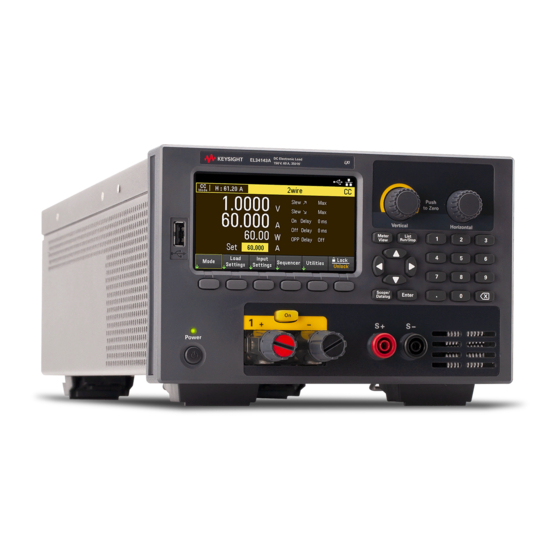
Product Introduction The EL30000 Series DC electronic loads are designed with superior performance in compact bench form factor. Ideal for design/verification of consumer power supplies, batteries, battery modules, solar panels, LED drivers, as well power converters. The series includes single and dual inputs models: –... - Page 17 USB/LAN standard, USB/LAN standard, GPIB optional GPIB optional Maximum operating voltage/current 150 V/40 A 150 V/60 A 150 V/60 A Digital IO Scope view Input-parallel mode Input sequencing Low range current measurement Data logging BenchVue software Keysight EL30000 Series User's Guide...
-
Page 18: Front Panel At A Glance (El33133A/El34143A)
Turns on the instrument. If the LED is amber, the instrument is in standby mode with AC inlet power connected, and if it is green, the instrument is on. Softkeys Accesses the soft front panel menu. Keysight EL30000 Series User's Guide... -
Page 19: Front Panel At A Glance (El34243A)
– Enters numeric values. Press [Enter] key to complete the entry. – Deletes the values entered into the dialog using the back key. Input On key Turns individual inputs On or Off; inputs are on when the key is lit. Input terminals Keysight EL30000 Series User's Guide... -
Page 20: Rear Panel At A Glance (El33133A/El34143A)
GPIB port (EL34143A only – Option GPIB) USB port (EL34143A only) LAN port (EL34143A only) Digital I/O terminal port (EL34143A only) Fan ventilation hole Input 1 terminal port with mating connector Input 1 sense terminal port Keysight EL30000 Series User's Guide... -
Page 21: Rear Panel At A Glance (El34243A)
AC inlet GPIB port (Option GPIB) USB port LAN port Digital I/O terminal port Fan ventilation hole Input 1 and input 2 terminal ports with mating connectors Input 1 and input 2 sense terminal ports Keysight EL30000 Series User's Guide... -
Page 22: Meter View
: The instrument is not connected to LAN. : The instrument is connected to LAN. (blinking): The LAN connection is at fault. (blinking): The instrument is under identification mode via remote interface. Slew rate Displays the rising slew and falling slew rate Keysight EL30000 Series User's Guide... - Page 23 Displays the present input value settings in voltage, ampere, ohms and watts. Use the numeric keypad or turn the front panel knob to adjust these settings. Input short indicator Displays when input short is enabled. Input meters Displays the actual input voltage. current and power. Keysight EL30000 Series User's Guide...
-
Page 24: Data Logger View
Measurement Marker 2 enabled. This can be adjusted using the Horizontal knob after pressing Knob Mrk. Intersect point Shows where the measurement markers intersect the waveform. Measurements Shows the calculations of the waveform data between Marker 1 and Marker 2. Keysight EL30000 Series User's Guide... -
Page 25: Scope View
Measurement Marker 1 enabled. This can be adjusted using the Vertical knob after pressing Knob Mrk. m2 marker Measurement Marker 2 enabled. This can be adjusted using the Horizontal knob after pressing Knob Mrk. Keysight EL30000 Series User's Guide... -
Page 26: Dimension Diagram
Before disconnecting cables and cords from the instrument, turn the instrument off using the front-panel [Power] key and disconnect from the supply source by unplugging the detachable power cord. Keysight EL30000 Series User's Guide... -
Page 27: Prepare Instrument For Use
– Two 85 A, 12 mm 2-pin mating connector Documentation and firmware revisions The Keysight EL30000 Series documentation listed below can be downloaded for free through our website at www.keysight.com/find/el30000. – Keysight EL30000 Series DC Electronic Load User's Guide. This manual. -
Page 28: Load Operating Modes
Load Operating Modes The load operating modes for Keysight EL30000 Series DC electronic load are: – Constant current (CC) mode – Constant voltage (CV) mode – Constant power (CP) mode – Constant resistance (CR) mode When programmed to a mode, the electronic load remains in that mode until the mode is changed or until a fault condition, such as an overpower or over-temperature occurs. -
Page 29: Cv Mode
Voltage may be programmed in one of two overlapping ranges, a Low and a High range. The low range provides better programming and measurement resolution at low voltage settings. CP mode In this mode, the load unit will regulate the power being drawn from the DUT according to the programmed constant-power value. Keysight EL30000 Series User's Guide... -
Page 30: Cr Mode
If the resistance value falls in a region where ranges overlap, the load selects the range with the highest resolution for the resistance value. Keysight EL30000 Series User's Guide... -
Page 31: Programming Ranges
Programming Ranges The following table shows the input ranges (voltage, current, power and resistance) and its default value that can be programmed for each model in EL30000 Series. Operating Range EL33133A EL34143A EL34243A Mode High MAXimum 153 V 153 V... - Page 32 Single: 10 Ω Parallel: 5 Ω MAXimum 30 Ω 30 Ω Single: 30 Ω Parallel: 15 Ω MINimum 0.08 Ω 0.05 Ω Single : 0.05 Ω Parallel: 0.025 Ω DEFault (*RST) 4 kΩ 100 kΩ 100 kΩ Keysight EL30000 Series User's Guide...
-
Page 33: Installation
Connect the power cord to the AC inlet connector on the rear of the unit. If the wrong power cord was shipped with your unit, contact your nearest Keysight Sales and Support Office. Removing the power cord will disconnect AC input power to the unit. Keysight EL30000 Series User's Guide... -
Page 34: Connecting The Inputs
If you are using a slotted screwdriver, tighten the binding post to 8 in-lb (90 N-cm) for a secure connection. Maximum current rating: (A) = 60 A Keysight EL30000 Series User's Guide... - Page 35 To satisfy safety requirements, load wires must be heavy enough not to overheat while carrying the short-cir- cuit output current of the DUT connected to electronic load. Ampacity Resistance (Ω/m) 0.0103 0.0065 0.0041 0.0025 0.0016 0.0010 0.00064 Keysight EL30000 Series User's Guide...
- Page 36 21 - 25 1.08 26 - 30 1.00 31 - 35 0.91 36 - 40 0.82 41 - 45 0.71 46- 50 0.58 51 - 55 0.41 2. Resistance is nominal at 75 °C wire temperature. Keysight EL30000 Series User's Guide...
-
Page 37: Parallel Connections (El34243A Only)
Parallel connections (EL34243A only) Equipment Damage Only connect inputs that have identical voltage and current ratings in parallel. Keysight EL30000 Series electronic loads can be paralleled, but ONLY when operated in CC, CR and CP mode. CV mode is not allowed. - Page 38 Keysight EL30000 Series User's Guide...
-
Page 39: 4-Wire Sense Connection
However, any voltage drop in the sense leads can degrade the voltage regulation of the instrument. After turning the unit on, activate 4-wire remote voltage sensing by pressing Source Settings > Sense 4w . Refer to Specifying 2-Wire or 4-Wire Sense. Keysight EL30000 Series User's Guide... - Page 40 Twist the sense leads or use a ribbon cable to minimize the pickup of external noise. In extremely noisy environments it may be necessary to shield the sense leads. Ground the shield at the electronic load end only; do not use the shield as one of the sensing conductors. Keysight EL30000 Series User's Guide...
-
Page 41: Interface Connections
4. The electronic load is shipped with its GPIB address set to 5. Use the front panel menu if you need to change the GPIB address. 5. You can now use Interactive IO within the Connection Expert to communicate with your instrument, or you can program your instrument using the various programming environments. Keysight EL30000 Series User's Guide... - Page 42 2. Use the Connection Expert utility of the Keysight IO Libraries Suite to add the electronic load and verify a connection. To add the instrument, you can request the Connection Expert to discover the instrument. If the instrument cannot be found, add the instrument using its hostname or IP address. Keysight EL30000 Series User's Guide...
- Page 43 If this does not work, refer to “Troubleshooting Guidelines” in the Keysight Technologies USB/LAN/GPIB Inter- faces Connectivity Guide included with the Keysight IO Libraries Suite. 3. You can now use Interactive IO within the Connection Expert to communicate with your instrument, or you can program your instrument using the various programming environments.
- Page 44 Positive polarity is selected, a logical true signal is a voltage high at the pin. When Negative polarity is selected, a logical true signal is a voltage low at the pin. For more information on configuring the digital port functions, refer to Using the Digital Control Port. Keysight EL30000 Series User's Guide...
-
Page 45: Installing The Optional Gpib Interface (El34143A And El34243A Only)
Attach the cable to the connector located in the Put the module into the unit. Use the screws that previous step. was removed earlier to secure the GPIB plate in place. This concludes the GPIB installation procedure. Keysight EL30000 Series User's Guide... -
Page 46: Rack Mounting The Instrument
To rack mount two instruments side-by-side, order lock-link kit (5061-8769). Be sure to use the support rails in the rack cabinet. Rackmount kit without handles (1CM104A) Front handle kit (1CN107A) Rackmount kit with handles (1CP108A) Keysight EL30000 Series User's Guide... -
Page 47: Remote Interface Configuration
1. Press Utilities > I/O Config > GPIB to access the GPIB window. 2. From this window, you can set the GPIB address using the numeric keys and press [Enter] . 3. Press Back to exit. Keysight EL30000 Series User's Guide... -
Page 48: Lan Configuration
All default LAN settings are listed under Non-volatile Settings in Programming Guide. Press Utilities > I/O Config > LAN Status > LAN Reset resets the LAN using its current settings and enables DHCP and DNS. The LAN Reset softkey also clears any user-defined Web Interface password. Keysight EL30000 Series User's Guide... - Page 49 4. Press No to cancel all the changes and exit without saving. To manually set an IP address, Subnet Mask, or Default Gateway, press DHCP Off . Then, change the IP setup as described below. Keysight EL30000 Series User's Guide...
- Page 50 2. Select Gateway field using the navigation keys. Set the appropriate gateway address and press Back . 3. Press Yes to save the setting. 4. Press No to cancel all the changes and exit without saving. Keysight EL30000 Series User's Guide...
- Page 51 2. Select DNS Hostname field using the navigation keys. Press and enter the hostname with the keyboard provided. Press Back . 3. Press Yes to save the setting. 4. Press No to cancel all the changes and exit without saving. Keysight EL30000 Series User's Guide...
-
Page 52: Using Sockets
When the SRQ value is true, the instrument will send the string "SRQ +nn" to the client. The "nn" is the status byte value, which the client can use to determine the source of the service request. Keysight EL30000 Series User's Guide... -
Page 53: More About Ip Addresses And Dot Notation
"192.168.020.011" is equivalent to decimal "192.168.16.9" because ".020" is 16 expressed in octal, and ".011" (octal) is "9" (base 10). To avoid confusion, use only decimal values from 0 to 255, with no leading zeros. Keysight EL30000 Series User's Guide... -
Page 54: Remote Control
Check the checkbox below the picture of the instrument to enable an indicator on the instrument's front panel. This is helpful if you have several EL30000 Series instruments and you wish to identify the one to which you are connected. - Page 55 "rotate" the knob. You can press the arrow keys to rotate the knob clockwise and counter- clockwise, just as you would press any of the other keys on the front panel. READ WARNING Be sure to read and understand the warning at the top of the Control Instrument page. Keysight EL30000 Series User's Guide...
-
Page 56: Technical Connection Details
Port number 80, URL http://<IP address>/ USB0::0x2A8D::<Prod ID>::<Serial Number>::0::INSTR Example: USB0::0x2A8D::0x0902::MY55160003::0::INSTR The vendor ID: 0x2A8D, the product ID is 0x0902, and the instrument serial number is MY55160003. The product ID varies by model: 0x3702 (EL33133A), 0x3802 (EL34143A), and 0x3902 (EL34243A). Keysight EL30000 Series User's Guide... -
Page 57: Use The Built-In Help System
Press Utilities > Test / Setup > Help to view the list of help topics. Press the arrow softkeys or use the front panel arrow keys to highlight the desired topic. Then press Select . In this case, the following help topic appears: Keysight EL30000 Series User's Guide... - Page 58 Russian. To select the local language, press Utilities > Test / Setup > User Settings > Display Options > Help Lang. . Then select the desired language. The menu softkey labels and status line messages are not trans- lated. Keysight EL30000 Series User's Guide...
-
Page 59: Firmware Update
Otherwise, download the firmware update utility and a ZIP file of the firmware. Detailed firmware update instructions are located on the download page. Keysight EL30000 Series User's Guide... -
Page 60: Front Panel Menu Reference
Creates, copies, deletes, and renames files and folders on the USB drive attached to the front panel. Also allows you to capture the current screen to either a bitmap (*.bmp) or portable network graph- ics (*.png) file. Lock | Unlock Locks and unlocks the display. Keysight EL30000 Series User's Guide... -
Page 61: General Operating Information
Using the Scope Function Locking/Unlocking the Front Panel Capturing a Screen Utilities Menu This chapter describes the general operating information of the EL30000 Series. For the characteristics and specifications of the EL30000 Series DC electronic loads, refer to the datasheet at https://www.keysight.com/my/en/assets/3120-1430/data- sheets/EL30000-Series.pdf. -
Page 62: Turning The Unit On
A power-on self-test occurs automatically when you turn the unit on. This assures you that the instrument is operational. If self-test fails, or if other operating problems occur with your instrument, the front panel error indicator (!Err) appears at the upper top of the display. Keysight EL30000 Series User's Guide... -
Page 63: Using The Front Panel Knobs
– Except for self-test errors, errors are cleared when exiting the Error Log menu or when cycling power. If you suspect that there is a problem with the electronic load, refer to the "Troubleshooting" section in the Service Guide . Keysight EL30000 Series User's Guide... -
Page 64: Controlling The Inputs
You can also enter the voltage, current, resistance, or power values directly in the numeric entry fields (the Set fields) in the meter-view display. Use the navigation keys to select the field; use the numeric entry keys to enter the value. The value becomes active when you press [Enter] . Keysight EL30000 Series User's Guide... -
Page 65: Step 4 - Enable The Input
The following meter view applies to CC mode. CV, CP, and CR mode views are similar. All measurements have an over-range capability of 10% above the maximum range limit. If the measurement exceeds this limit, “Data Out of Range” error will occur Keysight EL30000 Series User's Guide... - Page 66 To enable only input 1: INP ON, (@1) To enable input 1 and input 2: INP ON, (@1,2) To measure the average input voltage, current, and power of input 1: MEAS:VOLT? (@1) MEAS:CURR? (@1) MEAS:POW? (@1) Keysight EL30000 Series User's Guide...
-
Page 67: Using The Protection Function
With over-current protection enabled, the load disables the input if the input current reaches the current limit setting, which causes a transition from CV to CC mode. Press OCP State On to enable over-current protection. Keysight EL30000 Series User's Guide... - Page 68 Press OCP State Off to disable over-current protection. The EL30000 Series has fixed over-current protection that is always enabled. This protection will turn the input off whenever the input current exceeds 105% of the high ranges and approximately 110% of the low cur- rent ranges.
-
Page 69: Clears Ovp, Ocp And Opp Event
To set the over-power protection delay time for input 1 at 0.2 seconds: POW:PROT:DEL 0.2, (@1) To program a low-voltage limit (under-voltage inhibit) of 2 V, and enable the inhibit mode: VOLT:INH:VON 2, (@1) VOLT:INH:VON:MODE LIVE, (@1) To clear protection for input 1: INP:PROT:CLE (@1) Keysight EL30000 Series User's Guide... -
Page 70: Specifying 2-Wire Or 4-Wire Sense
4-wire sense is disabled. The 4w mode opens the relay in order to separate the input and 4-wire sense inputs. By default, 2w is selected. From the remote interface: To set the remote sense relay to 4-wire sense at input 1: VOLT:SENS EXT, (@1) Keysight EL30000 Series User's Guide... -
Page 71: Configuring The Input Turn-On/Turn-Off Sequence
– Press Coup CH 2 to toggle between Off and On in order to turn off or on the coupling for Input 2. (applicable for EL34243A only) Step 4 – Use the All Inputs On and Off keys: Once input delays have been set, press [All On/Off] to start the On delay and Off delay sequence. Keysight EL30000 Series User's Guide... - Page 72 INP:DEL:RISE 0.01, (@1) INP:DEL:RISE 0.02, (@2) INP:DEL:FALL 0.04, (@1) INP:DEL:FALL 0.03, (@2) To only include inputs 1 and 2 in a sequence: INP:COUP:CHAN CH1,CH2 To turn on two coupled inputs in a sequence: INP ON (@1:2) Keysight EL30000 Series User's Guide...
-
Page 73: Specifying The Load Operating Mode
Specifying the Load Operating Mode The operating modes of operation for Keysight EL30000 Series electronic load are: – Constant current (CC) : In this mode, the electronic load will sink a current in accordance with the pro- grammed value regardless of the input voltage. Note that a programmable voltage limit is not available. If the DUT imposes a voltage above the voltage rating of the module, the overvoltage protection will trip. -
Page 74: Configuring The Load Settings
Configuring the Load Settings Press Load Settings to access the available configuration for the EL30000 Series. Operating modes Press Mode to select one of the four operating modes (CC, CV, CR and CP). The parameters in Load Settings page will change accordingly to the selected operating mode. - Page 75 In this mode, the load will sink a current linearly proportional to the voltage in accordance with the programmed resistance value. Resistance - Lets you enter a resistance value with the numeric keys. Press Enter to enter the value. You can also use the knob to adjust the value in this field. Keysight EL30000 Series User's Guide...
- Page 76 FUNC POW, (@1) To set the voltage to 10 V, the current to 5 A, the resistance to 100 Ω, and power to 50 W: VOLT 10, (@1) CURR 5, (@1) RES 100, (@1) POW 50, (@1) Keysight EL30000 Series User's Guide...
- Page 77 To set the negative current slew, turn coupling (tracking) off. Then set the negative current slew: CURR:SLEW:COUP OFF, (@1) CURR:SLEW:NEG 3, (@1) To set the sense terminals to remote sensing: VOLT:SENS:SOUR EXT, (@1) To query the setting of the sense terminals: VOLT:SENS:SOUR? (@1) Keysight EL30000 Series User's Guide...
-
Page 78: Specifying The Operation Mode (El34243A Only)
2. Press Independant or Parallel to select the desired operation mode. 3. Press Back to exit. For input connection in Input-Parallel mode, see Parallel Connections for details. From the remote interface: To enable Input-parallel mode: INP:PAIR PAR Keysight EL30000 Series User's Guide... -
Page 79: Using The Digital Control Port
The digital I/O pin can be used to control both relay circuits as well as digital interface circuits. The figure above illustrates typical relay circuits as well as digital interface circuit connections using the digital I/O functions. Keysight EL30000 Series User's Guide... - Page 80 To configure the pin polarity to positive for pins 1 through 3: DIG:PIN 1:POL POS DIG:PIN 2:POL POS DIG:PIN 3:POL POS To send a binary weighted value to configure pins 1 through 3 as “111”: DIG:OUTP:DATA 7 Keysight EL30000 Series User's Guide...
-
Page 81: Digital Input
The polarity of pin 1 can also be configured. Note that the fault output signal remains latched until the fault condition is removed and the protection circuit is cleared. Pin 2's selected function is ignored. Pin 2 should be connected to the ground of the external circuit. Keysight EL30000 Series User's Guide... -
Page 82: Inhibit Input
Alternatively, you can configure Pin 3 as a remote inhibit input by pressing Input Settings > Output Inhibit > DIO Pin 3 INH . In this setting, the polarity is set to Positive by default. Keysight EL30000 Series User's Guide... -
Page 83: Fault/Inhibit System Protection
Note that when using the Fault/Inhibit signals in this manner, both signals must be set to the same polarity. Keysight EL30000 Series User's Guide... -
Page 84: Trigger Input
4. Configure the polarity for each of the pin. Press Polarity Pos to select Positive and Polarity Neg to select Neg- ative. Select and program the remaining pins in the same manner. Keysight EL30000 Series User's Guide... -
Page 85: Trigger Output
4. Configure the polarity for each of the pin. Press Polarity Pos to select Positive and Polarity Neg to select Neg- ative. Select and program the remaining pins in the same manner. From the remote interface: To select the trigger output function: DIG:PIN1:FUNC TOUT To select the pin polarity: DIG:PIN1:POL POS DIG:PIN1:POL NEG Keysight EL30000 Series User's Guide... -
Page 86: Input Couple Controls
3. Connect and configure the digital connector pins of the synchronized loads as described in this section. All synchronized EL30000 Series electronic loads must have the same firmware revision. Only pins 1 through 3 can be configured as synchronization pins. You cannot configure more than one On Couple and one Off Couple pin per electronic load. - Page 87 Off keys, the Web server, and to SCPI commands. Turning the load inputs on or off using the front panel [All On/Off] key will cause all coupled inputs as well as non- coupled inputs on that load to turn on or off. Keysight EL30000 Series User's Guide...
-
Page 88: Using The Sequencer Function (El34143A And El34243A Only)
7. Set the list repeat count. 8. Set the list to repeat continuously. You can configure up to 100 steps in the Sequencer LIST window. Step 1– Add/remove steps to/from the LIST Press Sequencer to access the Sequencer LIST window. Keysight EL30000 Series User's Guide... -
Page 89: Step 2 - Configure The Input Sequence
Enables check box to set which step will generate a trigger-out signal at the end of the step (EOST). For additional settings, press Properties to open the Sequencer LIST Properties window. Configure the Sequencer LIST accordingly. Refer to the below table for details. Keysight EL30000 Series User's Guide... - Page 90 Fix (Fixed) Keeps the input at its immediate value. Stp (Step) Steps the input to the triggered level when a trigger occurs Lst (List) Causes the input to follow the list values when a trigger occurs. Keysight EL30000 Series User's Guide...
-
Page 91: Step 3 - Run The Input Sequence List
– Press the color-coded [On] key to enable the selected input. – Press Run to start the list operation. To abort the operation, press Stop . – Press Back to exit and return to the previous menu. Keysight EL30000 Series User's Guide... - Page 92 To set the current mode of input 1 to List: CURR:MODE LIST, (@1) To set the trigger source of input 1 to Key/Immediate: TRIG:SOUR IMM, (@1) To enable input 1: INP ON, (@1) To initiate the transient operation sequence: INIT:TRAN, (@1) Keysight EL30000 Series User's Guide...
-
Page 93: Continuous Mode
Fix (Fixed) Keeps the input at its immediate value. Stp (Step) Steps the input to the triggered level when a trigger occurs Lst (List) Causes the input to follow the list values when a trigger occurs. Keysight EL30000 Series User's Guide... -
Page 94: Step 2 - Run The Input Sequence
– Press the color-coded [On] key to enable the selected input. – Press Run to start the sequence operation. To abort the operation, press Stop . – Press Back to exit and return to the previous menu. Keysight EL30000 Series User's Guide... - Page 95 To set the trigger source of input 1 to Key/Immediate: TRIG:TRAN:SOUR IMM, (@1) To configure the input voltage to follow transient value when a trigger occurs: VOLT:MODE LIST To enable input 1: INP ON, (@1) To initiate the transient operation sequence: INIT:TRAN, (@1) Keysight EL30000 Series User's Guide...
-
Page 96: Pulse Mode
Fix (Fixed) Keeps the input at its immediate value. Stp (Step) Steps the input to the triggered level when a trigger occurs Lst (List) Causes the input to follow the list values when a trigger occurs. Keysight EL30000 Series User's Guide... -
Page 97: Step 2 - Run The Input Sequence
– Press the color-coded [On] key to enable the selected input. – Press Run to start the sequence operation. To abort the operation, press Stop . – Press Back to exit and return to the previous menu. Keysight EL30000 Series User's Guide... - Page 98 To set the trigger source of input 1 to Key/Immediate: TRIG:TRAN:SOUR IMM, (@1) To configure the input voltage to follow transient value when a trigger occurs: VOLT:MODE LIST To enable input 1: INP ON, (@1) To initiate the transient operation sequence: INIT:TRAN, (@1) Keysight EL30000 Series User's Guide...
-
Page 99: Toggle Mode
Selects any configured digital IO (with Trigger Input function) as a trigger source Rmt (Remote Command) Selects a remote interface command as a trigger source. Trigger Delay 0 to 0.255 s Sets the trigger delay in seconds. Default is 0 s. Keysight EL30000 Series User's Guide... -
Page 100: Step 2 - Run The Input Sequence
To set the trigger source of input 1 to Key/Immediate: TRIG:TRAN:SOUR IMM, (@1) To configure the input voltage to follow transient value when a trigger occurs: CURR:MODE LIST To enable input 1: INP ON, (@1) To initiate the transient operation sequence: INIT:TRAN, (@1) Keysight EL30000 Series User's Guide... -
Page 101: Using The Data Logger Function
Configure the input sequence as described under Using the Sequence LIST. Program the input current and time values as follows: Step 0: 0.5 A; 1 s Step 1: 1 A; 1 s Step 2: 2 A; 1 s Keysight EL30000 Series User's Guide... -
Page 102: Step 4 - Configure The Data Logger Traces
Traces are color coded according to input. The ground symbol on the right side of the display indicates the ground reference of the trace. Step 5 – Configure the data logger properties Press Properties to display the Data Logger properties field. Keysight EL30000 Series User's Guide... -
Page 103: Step 6 - Configure And Enable The Dut Output Accordingly
Press File Name located at the data logger Properties menu to specify a filename. Step 8 – Export the data After you have completed the data logging, you can use the Export File key to export the logged data to a .csv (comma separated values) file. Keysight EL30000 Series User's Guide... - Page 104 SENS:DLOG:PER 0.2 To initiate that data logger and specify the filename in which to save the data: TRIG:DLOG:SOUR BUS INIT:DLOG “External:\log1.csv” To turn on Input 1 and run the data logger: INP ON, (@1) *TRG Keysight EL30000 Series User's Guide...
-
Page 105: Data Logger View
Indicates the trigger position in the data log. In this example the trigger point was offset by 0%, and the pre trigger and post trigger data was logged. The time at the trigger point is always zero. Change the trigger offset in the Data Logger Logging Settings. Keysight EL30000 Series User's Guide... -
Page 106: Data Logger Marker View
If a marker is out of view, an arrow indic- ates the direction of the marker Delta Indicates the delta or absolute difference between the markers in units (volts, amps, or watts) and in time (seconds). Keysight EL30000 Series User's Guide... -
Page 107: Using The Knob In Data Logger View
Use the navigation keys to select the trigger level located on the left pane of data logger view, as shown below. Adjusting the Vertical or Horizontal knob will adjust the trigger level for Voltage level, or Current level accordingly. Keysight EL30000 Series User's Guide... -
Page 108: Data Logger Properties And Waveform Settings
If the file size exceeds the available space on the drive to which it will be written, an error is generated and the Data Logger will not run. Keysight EL30000 Series User's Guide... - Page 109 Returns the Data Logger View to the power-on display settings. Navigate Verr, Hor or Log Selects the Vertical Settings, Horizontal Settings or Logging Set- tings field. Action required: Press Navigate to toggle between Ver, Hor and Log. Keysight EL30000 Series User's Guide...
- Page 110 50%, the Data Logger will log 15 minutes of pre-trig- ger data to the file before the trigger occurs. Subsequently, 15 minutes of post-trigger data will then be logged to the data file. Keysight EL30000 Series User's Guide...
- Page 111 To select the immediate trigger source (triggers the Data Logger immediately when initiated): TRIG:DLOG:SOUR IMM To select the rear panel trigger input (all connector pins that have been configured as trigger sources): TRIG:DLOG:SOUR EXT To select a BUS trigger source: TRIG:DLOG:SOUR BUS Keysight EL30000 Series User's Guide...
-
Page 112: Save The Data Log
Press Save Path to browse and specify the location where the data log will be saved. Use the front-panel navigation keys to navigate through the list. The left and right arrows contract or expand a folder to hide or show its files. Keysight EL30000 Series User's Guide... - Page 113 Press Export File to export the data that is currently in the instrument's data log viewer to file. The exported data is in .csv format. For details on how to specify the save location and filename, refer to Save the Data Log. Keysight EL30000 Series User's Guide...
- Page 114 Press Browse to browse and select file from the directory. You can select from the internal memory or external memory (USB drive). Press Select to select the file or Cancel to abort. Press Load to load the file. Keysight EL30000 Series User's Guide...
-
Page 115: Using The Scope Function
In Meter View, set the input current of input 1 to 1 A. This is described under Controlling the Inputs. Step 3 - Configure the input turn-on sequence Configure the input turn-on sequence as described under Configuring the Input Turn-On/Turn-Off Sequence. Keysight EL30000 Series User's Guide... -
Page 116: Step 4 - Configure The Scope View Traces
– Press Trigger Mode > Single to display a single sweep measurement. Press Back twice to return to the Scope Properties menu. – Set the Time Reference to Left in Horizontal Settings (Hr) window: Press Settings > Time Ref Lf . Keysight EL30000 Series User's Guide... -
Page 117: Step 6 - Configure And Enable The Dut Output Accordingly
– Press Input 1 [On] key to start the input sequence and trigger the scope. You should see the input waveforms displayed as follows: From the remote interface: You cannot program the scope from the remote interface. Keysight EL30000 Series User's Guide... -
Page 118: Scope View
Shows the location of the voltage or current trigger level and input. In this example, the voltage trig- ger level of input 1 is shown. The trigger source and amplitude are shown at the left corner of the dis- play. Keysight EL30000 Series User's Guide... - Page 119 Using knob in scope view. Marker On or Off Enables or disables the Marker view. Properties Sets the scope and waveform displays properties. See Scope properties and waveform settings. Auto Scale Auto scales the traces on the display. Keysight EL30000 Series User's Guide...
-
Page 120: Scope Marker View
Time indicates the time between markers over which the average value is calculated. RMS (if selected) Calculates the rms value between the marker locations. Vp-p (if selected) Calculates the difference between the maximum and minimum values. Time information is not valid for calculated p-p values. Keysight EL30000 Series User's Guide... -
Page 121: Using The Knob In Scope View
Use the navigation keys to select the trigger level located on the left pane of scope view, as shown below. Adjusting the Vertical or Horizontal knob will adjust the trigger level for Voltage level, or Current level accordingly. Keysight EL30000 Series User's Guide... -
Page 122: Scope Properties And Waveform Settings
Specifies a trigger source. This trigger source will trigger the scope measurements (Trg) on all input channels. Level Specifies a trigger level if you select a Voltage level or Current level as the trigger source. Mode Specifies a trigger mode. Slope Specifies a trigger slope. Keysight EL30000 Series User's Guide... - Page 123 The offset is referenced to the horizontal center line of the grid. Navigate Ver, Hor or Trg Selects the Vertical Settings, Horizontal Settings or Trigger Settings field. Action required: Press Navigate to toggle between Ver, Hor and Trg. Keysight EL30000 Series User's Guide...
- Page 124 All Inputs On/Off key. IO (DIO Trigger In) Selects any configured digital IO (with Trigger Input function) as a trigger source. Remote (Remote Selects a remote interface command as a trigger source. Command) Keysight EL30000 Series User's Guide...
-
Page 125: Scope Marker Properties
Measurements apply to the portion of the waveform between the two markers. You can only select a maximum of three measurements to be displayed. Save the scope data Refer to Save the data log for information on how to save the scope data. Keysight EL30000 Series User's Guide... -
Page 126: Locking/Unlocking The Front Panel
Press [Meter View] for more than three seconds to capture a screen. The screen that was active will be saved to the USB flash storage connected to the front USB port. To configure the screen capture storing path, refer to Utilities Menu - Manage Files for details. Keysight EL30000 Series User's Guide... -
Page 127: Utilities Menu
– Operation mode (Independent or Parallel) – Input on/off sequencing – Sequencer settings – Trigger settings – Digital I/O input data and bus setting – Scope and data logger trigger source 1. Applicable for EL34243A only Keysight EL30000 Series User's Guide... -
Page 128: Store Settings
– External: The instrument's state is stored in the external USB drive. Browse Allows you to browse and specify the location of the external memory to save the state. Filename Specifies the filename. Use the virtual keyboard to enter your desired filename. Store Stores the state. Keysight EL30000 Series User's Guide... -
Page 129: Recall Settings
Select the state number that you want to recall from. Recall Recall the state. From: Ext allows you to recall an instrument's state from the external USB drive inserted in the front panel's USB port. Keysight EL30000 Series User's Guide... -
Page 130: Power On Setting
Power On selects the state that will be loaded at power-up. This can be either the factory default state (Default), or user-defined states (State 0 to State 9). Press Set Power On to save the setting. Set to Defaults Set to Defaults loads the instrument's factory default state. Keysight EL30000 Series User's Guide... -
Page 131: Utilities Menu - I/O Configuration
AutoDNS allows assignment of the DNS addresses. AutoDNS On automatically configures the addressing of the instrument in DNS server mDNS allows modification of the mDNS Service Name. Hostname allows modification of the instrument's DNS hostname. Keysight EL30000 Series User's Guide... -
Page 132: Digital Io
Out enables ( 1 ) or disables ( 0 ) the output data for the selected pin. GPIB (optional) GPIB allows you to set the GPIB address to a value from 0 to 30. After changing the address, cycle the instrument's power for the changes to take effect. Keysight EL30000 Series User's Guide... -
Page 133: Utilities Menu - Test / Setup
Test / Setup provides access to calibration, self-test, as well as configures user preferences, sets the date and time, and accesses the help: MEMORY SANITIZATION PROCEDURE Refer to the EL30000 Series Security Guide for instructions to perform a memory sanitization procedure that san- itizes all user-accessible instrument memory and restarts the instrument. Calibration Calibration accesses the instrument calibration procedure. -
Page 134: User Settings
Press Utilities > Test / Setup > Self Test to perform the complete self-test of the electronic load. It takes approximately 2 seconds for the self-test to complete. You can also perform a complete self-test from the remote interface, see the EL30000 Series Programming Guide for details. -
Page 135: Low Range
Low Range enables or disables low range current measurement. Help Help allows you to view the quick reference help topic. Use the arrow softkeys or front panel navigation keys to navigate the desired topic. Press Select to view the help content. Keysight EL30000 Series User's Guide... - Page 136 About allows you to view the instrument's model number, description, and serial number. Keysight EL30000 Series User's Guide...
-
Page 137: Utilities Menu - Error
– Except for self-test errors, errors are cleared when exiting the Error Log menu or when cycling power. If you suspect that there is a problem with the electronic load, refer to "Troubleshooting" in the Service Guide. Keysight EL30000 Series User's Guide... -
Page 138: Utilities Menu - Manage Files
Rename - To rename a file or folder, press Rename . Browse to the folder or file to be renamed and press Select . Press New Name , enter a new name and press Done . Press Perform Rename > Back . Keysight EL30000 Series User's Guide... -
Page 139: Browse
Previous Char and Next Char to move the cursor in the area where the name is entered. In the image below, there is no Next Char softkey because the cursor is at the end. Press Done to confirm the new filename or Cancel to abort. Keysight EL30000 Series User's Guide... -
Page 140: Characteristics And Specifications
Characteristics and Specifications For the characteristics and specifications of the EL30000 Series DC electronic load, refer to the datasheet at https://www.keysight.com/my/en/assets/3120-1430/data- sheets/EL30000-Series.pdf. Keysight EL30000 Series User's Guide... - Page 141 This information is subject to change without notice. © Keysight Technologies 2020 Edition 1, November 15, 2020 Printed in Malaysia EL34243-90000 www.keysight.com...
Need help?
Do you have a question about the EL30000 Series and is the answer not in the manual?
Questions and answers