Bose Panaray MA12 Service Manual
Hide thumbs
Also See for Panaray MA12:
- Technical foundation & discussion (36 pages) ,
- Installation manual (16 pages) ,
- User manual (2 pages)

Related Manuals for Bose Panaray MA12


Summary of Contents for Bose Panaray MA12
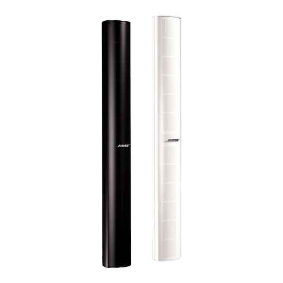
- Page 1 ® Panaray MA12 Modular Line Array Loudspeaker System ©2006 Bose Corporation Service Manual Reference Number 263639-SM Rev. 01 Electronic Copy Only...
-
Page 2: Table Of Contents
BY AN AUTHORIZED BOSE SERVICE CENTER OR OWNER OF THE BOSE PRODUCT, AND SHALL NOT BE REPRODUCED OR USED FOR ANY OTHER PURPOSE. Warranty The Bose Panaray MA12 Modular Line Array Loudspeaker System is covered by a limited 5-year transferable limited warranty. -
Page 3: Specifications
The Bose Panaray MA12 Loudspeaker can be used with the Bose Panaray MB4 Modular Bass Loudspeaker for dynamic full range reproduction. -
Page 4: Ma12 Loudspeaker System (See Figure 1)
MA12 Loudspeaker System (see Figure 1) ® Item Description Bose Part Vendor Part Qty. Note Number Number Number PACKING, END CAP 263624 1490-7393-0 POLYBAG 1497-5102-0 MA12 LOUDSPEAKER PACKING, CENTER 263625 1490-7433-1 OWNER’S MANUAL 263626 4301-5191-0 CARTON 263572 145A7780-0 Figure 1. Panaray MA12 Loudspeaker Packaging View... - Page 5 ENDCAP 259132-001 259132-002 GASKET, DRIVER 298549 298549 DRIVER, 2.25” 298550 298550 SCREW, BAFFLE, M4.5x12 SCREW, DRIVER, M3.5x8 U-CHANNEL, GRILLE LOGO, BOSE 298552-001 298552-002 GRILLE 298551-001 298551-002 U-CHANNEL FOR GRILLE COVER .35M GRILLE TRIM BARRIER TERMINAL SCREW, BARRIER TERMINAL, M3x14 CVT-12 TRANSFORMER...
- Page 6 Part List Panaray ® MA12 Loudspeaker Protection Circuit Board (see Figure 3) Item Description Part Number Qty. Note Number PCB ASSY, PROTECTION CKT 298553 LAMP, GREEN DOT 298554 POLYSWITCH, RXE075 298555-075 Figure 3. MA12 Protection Circuit Board Layout Diagram...
- Page 7 LAMP P P TC Screw Screw Terminal Terminal Figure 4. Panaray ® MA12 Loudspeaker Wiring Diagram...
-
Page 8: Disassembly Procedures
Disassembly Procedures Note: Refer to the figure below for the 2.3 Gently pull the grille assembly away following procedures. from the housing. Be careful not to mark the surface of the grille or the housing. 1. End Cap Removal 3. Driver Removal 1.1 Using a Phillips-head screwdriver, remove the six screws (4) that secure the 3.1 Perform procedure 2. -
Page 9: Test Procedures
Test Procedures Audio Signal Generator Power Amplifier INPUT OUTPUT Figure 5. Panaray ® MA12 Test Setup Diagram 1. Air Leak Test If the noise stays the same, it is normal suspension noise and the driver is fine. 1.1 Set up the system for test as shown in Suspension noise will not be heard with Figure 5. -
Page 10: Service Manual Revision History
Service Manual Revision History Date Revision Description of Change Change Driven Pages Level Affected 1/02 Document released at revision 00. Service manual release 10/06 Added RoHS compliant part numbers. RoHS initiative 4, 6... - Page 11 SPECIFICATIONS AND FEATURES SUBJECT TO CHANGE WITHOUT NOTICE Bose Corporation The Mountain Framingham Massachusetts USA 01701 P/N: 263639-SM Rev. 01 10/2006 (P) http://serviceops.bose.com...
Need help?
Do you have a question about the Panaray MA12 and is the answer not in the manual?
Questions and answers