
Related Manuals for Bose Panaray MB4


Summary of Contents for Bose Panaray MB4
- Page 1 ® Panaray MB4 Modular Bass Loudspeaker System ©2006 Bose Corporation Service Manual Reference Number 259321-SM Rev. 01 Electronic Copy Only...
-
Page 2: Table Of Contents
BY AN AUTHORIZED BOSE SERVICE CENTER OR OWNER OF THE BOSE PRODUCT, AND SHALL NOT BE REPRODUCED OR USED FOR ANY OTHER PURPOSE. Warranty The Bose Panaray MB4 Modular Bass Loudspeaker System is covered by a limited 5-year transferable limited warranty. -
Page 3: Specifications
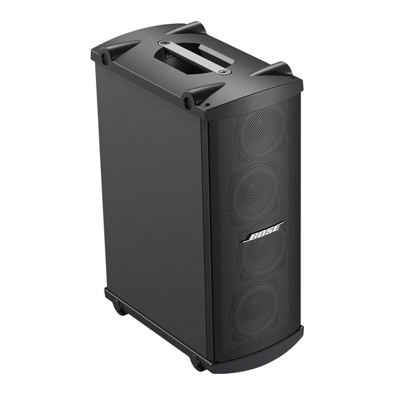
The Bose Panaray MB4 Modular Bass Loudspeaker System has two standard colors: black and white. The Panaray MB4 Modlular Bass Loudspeaker can be installed using an accessory wall mount bracket. -
Page 4: Packaging Part List, Panaray® Mb4 Bass Loudspeaker (See Figure 1)
Number Number PACKING FOAM 259317 145A-7570-0 OWNER’S MANUAL 259162 4301-5189-1 POLYBAG, 12” x 16” x 49” 1497-4552-0 MB4 BASS MODULE, BLACK 027054 FM000C MB4 BASS MODULE, WHITE 027055 FM001C CARTON 259316 145A-7590-0 Figure 1. Panaray MB4 Bass Loudspeaker Packaging View... -
Page 5: Main Part List, Panaray Mb4 Bass Loudspeaker System (See Figure 2)
Main Part List Panaray ® MB4 Bass Loudspeaker System (see Figure 2) Item Description Part Number Note Number Black White LOCKWASHER, LOGO SPRING, LOGO CUP WASHER, LOGO GRILLE GASKET GRILLE ASSY (WITH ITEMS 1, 2, 3 & 4) 298571 298572 SCREW, GRILLE, M4x28 298573 298573... -
Page 6: Disassembly Procedures
Disassembly Procedures 3. Woofer Assembly Removal Note: Refer to the figure below for the following procedures. 3.1 Perform procedure 2. 1. Terminal Panel Removal 3.2 Using a Phillips-head screwdriver, remove the four screws (14) that secure 1.1 Using a Phillips-head screwdriver, remove the four screws (11) that secure the the woofer assembly (13) that you wish to terminal panel (8) to the loudspeaker cabi-... -
Page 7: Test Procedures
Test Procedures Audio Audio Signa Signal Generato Generator Powe ower Am Ampli plifie ier INPU INPUT OUTPU OUTPUT Figure 3. Panaray ® MB4 Test Setup Diagram 1. Air Leak Test If the noise stays the same, it is normal suspension noise and the driver is fine. 1.1 Set up the system for test as shown in Suspension noise will not be heard with Figure 3. -
Page 8: Part List, Panaray Mb4 Bass Loudspeaker Protection Circuit Board (See Figure 3)
Part List Panaray ® MB4 Bass Loudspeaker Protection Circuit Board (see Figure 4) Item Description Part Number Qty. Note Number LAMP, GREEN DOT 298554 POLYSWITCH, RXE075 298555-075 Figure 4. MB4 Bass Loudspeaker Protection Board Layout... - Page 9 LAMP WOOFER WOOFER 1 protective protective lam lamp BLUE BLACK polyswitc polyswitch WOOFER WOOFER 2 YELL ELLOW WOOFER WOOFER 3 BLUE BLACK WOOFER WOOFER 4 ® Figure 5. Panaray MB4 Bass Loudspeaker Wiring Diagram...
-
Page 10: Service Manual Revision History
Service Manual Revision History Date Revision Description of Change Change Driven Pages Level Affected 1/02 Document released at revision 00. Service manual release 10/06 Added RoHS compliant part numbers. RoHS initiative 4, 5... - Page 11 SPECIFICATIONS AND FEATURES SUBJECT TO CHANGE WITHOUT NOTICE Bose Corporation The Mountain Framingham Massachusetts USA 01701 P/N: 259321-SM Rev. 01 10/2006 (P) http://serviceops.bose.com...
Need help?
Do you have a question about the Panaray MB4 and is the answer not in the manual?
Questions and answers