Table of Contents
Advertisement
Quick Links
IMPORTANT:
‐ The unit must impera vely be connected to a protec ve earth conductor.
‐ The unit must impera vely be protected by a 30 mA residual current circuit breaker .
‐ Only qualified and authorized personnel should open the electrical cabinet. Risk of electrical
shock or fire hazard. 230VAC.
‐ The unit must impera vely be installed a er the filter and must be the last element the wa‐
ter passes through before returning to the poll.
Rev. 15‐03‐2017
SALT WATER CHLORINATORS
SMC50‐SMC75
USER MANUAL
Advertisement
Table of Contents

Related Manuals for Innowater SMC50


Summary of Contents for Innowater SMC50
- Page 1 SALT WATER CHLORINATORS SMC50‐SMC75 USER MANUAL IMPORTANT: ‐ The unit must impera vely be connected to a protec ve earth conductor. ‐ The unit must impera vely be protected by a 30 mA residual current circuit breaker .
-
Page 2: Table Of Contents
CONTENTS 1. Security warnings…………………………………… 3 2. Unit descrip on …………………………………. 4 3. Control and power panel installa on……...5 4. Cell installa on………………….……...…………… 5 Cell housing Electrode assembly Flow switch Celle leads 5. Pump commissioning………………………………6 6. Electrical connec ons.…………………………….7 6. Opera on………………………………………………..7 6.1 Screen indica ons 6.2 ON/OFF switching 6.3 ON state: produc on ... -
Page 3: Security Warnings
1. SECURITY WARNINGS Before a emp ng the installa on or any manipula on on the unit make sure the it is disconnected from the power mains. The unit should be connected to a proper protec ve earth conductor. The unit should be protected by an external 30 mA residual circuit breaker. Do not operate the chlorinator if the pump is not running or if the flow through the celli is too low. ... -
Page 4: Unit Descrip On
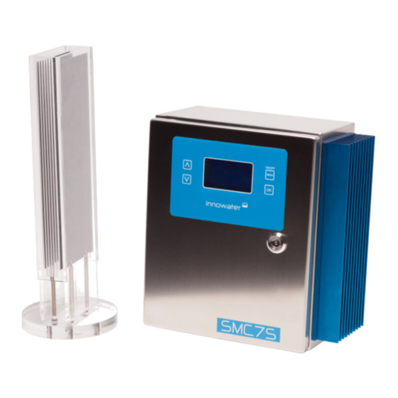
2 . UNIT DESCRIPTION 3 1 4 2 The SMC75 is an high performance electroly c chlorine generator. The unit produces pure chlorine, with‐ out any addi ves, directly from water with a salt concentra on above 4.0 gr/l. The chlorinator is installed in‐line in the pool filtra on circuit. Part of the return water flow is forced through the cell by means of a by‐ pass placed at the end of the circuit, once the water has passed through the filter and through any other element and just before the return to the pool. When passing through the cell, the water acquires a high and very effec ve chlorine concentra on capable of destroying most contaminants. The SMC75 main elements are: 1. Power and control cabinet. It houses the control and power units. 2. Control keyboard and display. 3. Cell housing. Its holds the electroly c cell and is powered by two cell cables and connectors. Two 63 mm unions are supplied. ... -
Page 5: Control And Power Panel Installa On
3. CONTROL AND POWER PANEL INSTALLATION Install the unit in a fresh and well ven lated place. Mount the panel on the wall using the supports on its back. The panel should impera vely be mounted upright. Keep any acid tanks away from the room where the unit has been installed. Acid vapours a ack metals including stainless steal and destroy electronic circuits. Keep the top of the panel and the heat sink area clear of any objects. 4. -
Page 6: Electrode Assembly
In order to effec vely evacuate the gas generated, the water outlet must always be above the water inlet. If the cell is installed ver cally, the water must enter the cell through the bo om inlet. Do not install the cell before the filter or any other element. The chlorinator cell must be the last ele‐ ment the water passes through before returning to the pool. Otherwise the gas generated in the cell could build up in the circuit and cause an explosion. -
Page 7: Electrical Connec Ons
Make sure that the voltage applied to the External Control Cable is 230VAC ONLY when the pump is running and the water flows freely through the cells and to the pool. 6. OPERATION The SMC50‐75 cell is controlled by means of a keyboard and a display. In a electroly c cell, chlorine genera‐ on is propor onal to the electrical current flowing through it .The SMC50‐75 will try to maintain a constant electrical current in the cell according to the chlorine produc on rate (0—100%) set by the user. The values of current and voltage in the cell are constantly displayed in the main screen. In normal condi ons and at ... - Page 8 Flow Switch ON/OFF: indicates produc on state. To toggle between ON and OFF press the MENU (ON/OFF) key for at least two seconds. Produc on se ng: Indicates the current chlorine produc on rate. It can be adjusted by pressing the ↑ o ↓ keys. I1, V1.: Indicate the cell working values and provide a valuable informa on for checking and diagnose. At 100% produc on rate and in normal condi ons I1 and I2 should be between: SMC50: 7.0 A to 8.5 A SMC75: 11.0 A to 13.5 A Tint: Cabinet interior temperature. Water: Water sensor state (— when not implemented). Cext: External control signal (signal read by the External Control Cable) Flow: Indicates the state of the flow switch. 6.2 Switching the unit ON and OFF To ...
-
Page 9: Display Messages
To control the chlorine produc on according to the pump running cycles or any other signal use the Exter‐ nal Control Cable as explained in sec on 5. DO NOT disconnect and reconnect the mains power supply ca‐ ble. ... -
Page 10: Menus
LOW SALT The es mated salt concentra on is lower than the op mum working range. The unit will remain in ON state and chlorine produc on will con nue normally. This message can also be displayed if the water is too cold, the electrodes are worn‐out or calcium has built up on the electrodes. SALT TOO LOW The es mated salt concentra on too low and out of the working range. The system will stop the produc on to avoid damage to the cell. This message can also appear if the cell is not properly connected. Press OK to confirm the message. The system will stop displaying the message and the unit will go to OFF state. Once the problem has been solved, the user can turn the unit ON again. PAUSE 04:54 When the system is carrying out a polarity inversion, the unit enters a pause mode and the remaining me is displayed on the screen. 8. MENUS To enter the menus, press the MENU key and move up or down between the different sub‐menus using the ↓ ↑ keys. To enter a par cular sub‐menu press OK. Once in a sub‐menu use ↓ o ↑ to change a parameter, MENU to go to the next parameter and OK to confirm and save changes. Then, use MENU once or more mes to come back to the Main Screen. ... -
Page 11: Regular Maintenance
The access to this menu requires a password. DO NOT enter this menu or try to change any of its parame‐ ters. Any parameter altera on will reconfigure the system and lead to a fail of the security systems. 9. REGULAR MAINTENANCE The SMC50‐75 requires a minimal maintenance that is basically reduced to the inspec on and cleaning of the cell and its connec ons. Nevertheless, this minimal maintenance is fundamental for good opera on and per‐ formance of the unit and to avoid future expensive failures. 9.1 Cell ... -
Page 12: Warnings
10. WARNINGS ‐ NEVER power the unit without being connected to a protec ve earth conductor. ‐ NEVER operate the chlorinator without an external 30 mA residual circuit breaker protec on. ‐ NEVER operate the chlorinator if the pump is not running or if the flow through the cells is too low.
Need help?
Do you have a question about the SMC50 and is the answer not in the manual?
Questions and answers