
Related Manuals for Riello NUOVO ACU Series


Summary of Contents for Riello NUOVO ACU Series
- Page 1 TECHNICAL INFORMATION ASSEMBLY, USE AND MAINTENANCE INSTRUCTIONS Water-Fed Fan Heaters NUOVO ACU SERIES...
-
Page 2: Warranty
RIELLO Technical Service only so as to ensure optimum performance at all times, low running costs and immediate availability of original spare parts. - Page 3 INDEX Conformity pag. 2 Range pag. 2 Warranty pag. 2 Notes for disposal pag. 2 Index pag. 3 General warnings pag. 4 Essential safety rules pag. 5 Description of the device pag. 6 Receiving the product pag. 6 Handling and transport pag.
-
Page 4: General Warnings
GENERAL WARNINGS This manual is an integral part of the machine, therefore it should always be carefully kept and it should always be provided together with the machine, if it is transferred to another owner or user. In case of damage or loss of this booklet, request another copy from your local Technical Assistance Service or Manufacturer. -
Page 5: Main Safety Rules
MAIN SAFETY RULES Bear in mind that if you use products powered trough electric power, gas, etc., you should comply with some basic rules, such as: This device cannot be used by people (including children) with reduced physical, sensory or mental abilities or lack of experience and knowledge, unless they are supervised or trained on the use of the unit by the person who is responsible for its safety. -
Page 6: Description Of The Unit
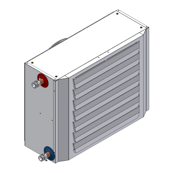
DESCRIPTION OF THE UNIT MODE OF OPERATION Water-fed fan heaters are designed to provide heating in winter and ventilation in summer. They are ideal for indoor areas such as shops, workshops and factories. Heating: The hot water produced by units such as the boiler or the heat pump in winter mode (not supplied), runs through one of the water-air exchangers which is brushed by an air flow generated by an electric axial helical fan running at three different speeds thanks to the accessory "variable speed switch with SUMMER/WINTER mode"... -
Page 7: Handling And Transport
HANDLING AND TRANSPORT Handling must be done by properly equipped personnel. Unit types 15-18 are packaged in a cardboard box with a wooden base. Raise the box with a fork-lift truck by inserting the forks in the special guides hollowed out in the support beams. All units are packaged in a cardboard box with handles for handling. -
Page 8: Dimensions And Weight
IDENTIFICATION The water-fed fan heaters can be identified by: The TECHNICAL DATA plaque (positioned on the rear of the unit) which shows the main technical/performance data. The packaging label that shows the code, model and serial number of the unit. In case of damage or loss, request a duplicate from Technical Assistance. - Page 9 STRUCTURE Structure of Heater Types 1 14 Water-air exchanger Fixing part Side panel, left Fixing part Side panel, right Fan(s) Upper-lower panel Outflow grating Internal part Structure of Heater Types 15 18 Water-air exchanger Fixing part Side panel, left Fixing part Side panel, right Fan(s)
-
Page 10: Technical Specifications
TECHNICAL SPECIFICATIONS TYPE 13.3 17.3 17.7 23.8 22.0 28.5 27.4 35.4 31.9 Thermal power (1) kcal/h 11,440 14,880 15,220 20,470 18,920 24,510 23,560 30,440 27,430 Rows n° Q.ty n° Axial fan Ø Rotations 1400 - 900 - 700 (3) Air flow rate m³/h 1,750 1,550... - Page 11 TECHNICAL DATA OF HEATING TYPES 1 AND 2, ELECTRICAL POWER SUPPLY SINGLE-PHASE 230 V 50 Hz, WATER TEMP. DROP 90-70°C Fan heater type 1 at maximum fan speed with water 90 – 70 °C Air intake temperature °C Thermal power 13.7 12.5 11.3...
- Page 12 TECHNICAL DATA OF HEATING TYPES 3 AND 4, ELECTRICAL POWER SUPPLY SINGLE-PHASE 230 V 50 Hz, WATER TEMP. DROP 90-70°C Fan heater type 3 at maximum fan speed with water 90 – 70 °C Air intake temperature °C Thermal power 18.1 16.6 15.1...
- Page 13 TECHNICAL DATA OF HEATING TYPES 5 AND 6, ELECTRICAL POWER SUPPLY SINGLE-PHASE 230 V 50 Hz, WATER TEMP. DROP 90-70°C Fan heater type 5 at maximum fan speed with water 90 – 70 °C Air intake temperature °C Thermal power 22.6 20.8 18.8...
- Page 14 TECHNICAL DATA OF HEATING TYPES 7 AND 8, ELECTRICAL POWER SUPPLY SINGLE-PHASE 230 V 50 Hz, WATER TEMP. DROP 90-70°C Fan heater type 7 at maximum fan speed with water 90 – 70 °C Air intake temperature °C Thermal power 28.1 25.8 23.4...
- Page 15 TECHNICAL DATA OF HEATING TYPES 9 AND 10, ELECTRICAL POWER SUPPLY SINGLE-PHASE 230 V 50 Hz, WATER TEMP. DROP 90-70°C Fan heater type 9 at maximum fan speed with water 90 – 70 °C Air intake temperature °C Thermal power 32.7 29.9 27.2...
- Page 16 TECHNICAL DATA OF HEATING TYPES 11 AND 12, ELECTRICAL POWER SUPPLY SINGLE-PHASE 230 V 50 Hz, WATER TEMP. DROP 90-70°C Fan heater type 11 at maximum fan speed with water 90 – 70 °C Air intake temperature °C Thermal power 40.1 36.6 33.2...
- Page 17 TECHNICAL DATA OF HEATING TYPES 13 14 15, ELECTRICAL POWER SUPPLY TRI-PHASE 400 V 50 Hz, WATER TEMP. DROP 90-70°C Fan heater type 13 at maximum fan speed with water 90 – 70 °C Air intake temperature °C Thermal power 48.6 44.5 40.3...
- Page 18 TECHNICAL DATA OF HEATING TYPES 16 17 18, ELECTRICAL POWER SUPPLY TRI-PHASE 400 V 50 Hz, WATER TEMP. DROP 90-70°C Fan heater type 16 at maximum fan speed with water 90 – 70 °C Air intake temperature °C Thermal power 90.4 82.6 74.9...
- Page 19 TECHNICAL DATA OF HEATING TYPES 1 AND 2, ELECTRICAL POWER SUPPLY SINGLE-PHASE 230 V 50 Hz, WATER TEMP. DROP 85-70°C Fan heater type 1 at maximum fan speed with water 85 – 70 °C Air intake temperature °C Thermal power 13.3 12.2 11,450...
- Page 20 TECHNICAL DATA OF HEATING TYPES 3 AND 4, ELECTRICAL POWER SUPPLY SINGLE-PHASE 230 V 50 Hz, WATER TEMP. DROP 85-70°C Fan heater type 3 at maximum fan speed with water 85 – 70 °C Air intake temperature °C Thermal power 17.7 16.2 14.7...
- Page 21 TECHNICAL DATA OF HEATING TYPES 5 AND 6, ELECTRICAL POWER SUPPLY SINGLE-PHASE 230 V 50 Hz, WATER TEMP. DROP 85-70°C Fan heater type 5 at maximum fan speed with water 85 – 70 °C Air intake temperature °C Thermal power 22.0 20.1 18.2...
- Page 22 TECHNICAL DATA OF HEATING TYPES 7 AND 8, ELECTRICAL POWER SUPPLY SINGLE-PHASE 230 V 50 Hz, WATER TEMP. DROP 85-70°C Fan heater type 7 at maximum fan speed with water 85 – 70 °C Air intake temperature °C Thermal power 27.4 25.0 22.6...
- Page 23 TECHNICAL DATA OF HEATING TYPES 9 AND 10, ELECTRICAL POWER SUPPLY SINGLE-PHASE 230 V 50 Hz, WATER TEMP. DROP 85-70°C Fan heater type 9 at maximum fan speed with water 85 – 70 °C Air intake temperature °C Thermal power 31.9 29.1 26.3...
- Page 24 TECHNICAL DATA OF HEATING TYPES 11, 12 AND 24, ELECTRICAL POWER SUPPLY SINGLE-PHASE 230 V 50 Hz, WATER TEMP. DROP 85-70°C Fan heater type 11 at maximum fan speed with water 85 – 70 °C Air intake temperature °C Thermal power 39.1 35.6...
- Page 25 TECHNICAL DATA OF HEATING TYPES 13 14 15, ELECTRICAL POWER SUPPLY TRI-PHASE 400 V 50 Hz, WATER TEMP. DROP 85-70°C Fan heater type 13 at maximum fan speed with water 85 – 70 °C Air intake temperature °C Thermal power 47.4 43.3 39.2...
- Page 26 TECHNICAL DATA OF HEATING TYPES 16 - 17 - 18, ELECTRICAL POWER SUPPLY TRI-PHASE 400 V 50 Hz, WATER TEMP. DROP 85-70°C Fan heater type 16 at maximum fan speed with water 85 – 70 °C Air intake temperature °C Thermal power 87.8...
- Page 27 TECHNICAL DATA OF HEATING TYPES 1 AND 2, ELECTRICAL POWER SUPPLY SINGLE-PHASE 230 V 50 Hz, WATER TEMP. DROP 50-40°C Fan heater type 1 at maximum fan speed with water 50 – 40 °C Air intake temperature °C Thermal power 5,150 4,200 3,250...
- Page 28 TECHNICAL DATA OF HEATING TYPES 3 AND 4, ELECTRICAL POWER SUPPLY SINGLE-PHASE 230 V 50 Hz, WATER TEMP. DROP 50-40°C Fan heater type 3 at maximum fan speed with water 50 – 40°C Air intake temperature °C Thermal power 6,800 5,550 4,150...
- Page 29 TECHNICAL DATA OF HEATING TYPES 5 AND 6, ELECTRICAL POWER SUPPLY SINGLE-PHASE 230 V 50 Hz, WATER TEMP. DROP 50-40°C Fan heater type 5 at maximum fan speed with water 50 – 40 °C Air intake temperature °C Thermal power 10.0 8,600 7,000...
- Page 30 TECHNICAL DATA OF HEATING TYPES 7 AND 8, ELECTRICAL POWER SUPPLY SINGLE-PHASE 230 V 50 Hz, WATER TEMP. DROP 50-40°C Fan heater type 7 at maximum fan speed with water 50 – 40 °C Air intake temperature °C Thermal power 12.4 10.1 10,650...
- Page 31 TECHNICAL DATA OF HEATING TYPES 9 AND 10, ELECTRICAL POWER SUPPLY SINGLE-PHASE 230 V 50 Hz, WATER TEMP. DROP 50-40°C Fan heater type 9 at maximum fan speed with water 50 – 40 °C Air intake temperature °C Thermal power 14.4 11.7 12,400...
- Page 32 TECHNICAL DATA OF HEATING TYPES 11 AND 12, ELECTRICAL POWER SUPPLY SINGLE-PHASE 230 V 50 Hz, WATER TEMP. DROP 50-40°C Fan heater type 11 at maximum fan speed with water 50 – 40 °C Air intake temperature °C Thermal power 17.5 14.2 10.4...
- Page 33 TECHNICAL DATA OF HEATING TYPES 13 - 14 - 15, ELECTRICAL POWER SUPPLY TRI-PHASE 400 V 50 Hz, WATER TEMP. DROP 50-40°C Fan heater type 13 at maximum fan speed with water 50 – 40 °C Air intake temperature °C Thermal power 21.3...
- Page 34 TECHNICAL DATA OF HEATING TYPES 16 - 17 - 18, ELECTRICAL POWER SUPPLY TRI-PHASE 400 V 50 Hz, WATER TEMP. DROP 50-40°C Fan heater type 16 at maximum fan speed with water 50 – 40 °C Air intake temperature °C Thermal power 39.7...
- Page 35 ACCESSORIES For the accessories, see the catalogue. To install the accessories, follow the instructions included in the relevant package. POSITIONING The location for the unit must be determined by the system designer or a competent person and it must take into account the technical requirements and the standards and regulations in force; generally, special permissions need to be obtained.
- Page 36 EXAMPLE OF POSITIONING Example of installation in a small room: Example of installation in a large room/area: Select the appropriate model on the basis of performance data for average fan speed. Do not install outside and in places with an aggressive environment...
- Page 37 Example of vertical installation To allow for proper air flow and therefore the correct operation of the unit, it is essential that there is no obstacle near the outlet nozzle side panel. Example of ceiling installation When mounting the heater on the ceiling it is recommended that you use the CEILING INSTALLATION KIT.
-
Page 38: Water Circuit Diagram
WATER COUPLING DIMENSIONS The unit is assembled in the factory with the water connection couplings on the left (as seen from the air outflow grating). Water fitting dimensions TYPE Unit Inches male WARNING!!! For optimum performance it is essential that water inlet-outlet directions always be observed as indicated by the adhesive label. -
Page 39: Water Connections
INVERTING THE WATER CONNECTIONS To switch the water connections from one side to the other proceed as follows: Disassemble the air outflow panel (1); Rotate the entire unit (2) 180°; Replace the air outflow panel (1). WARNING!!! For optimum performance it is essential that water inlet-outlet directions always be observed as indicated by the adhesive label. -
Page 40: Electrical Connections
ELECTRICAL CONNECTIONS The fan heater leaves the factory fully wired and need only: be connected to the mains; be connected to a control device (where applicable). WARNINGS: Install upstream of the unit a differential magneto thermal circuit breaker suitably sized according to the regulations in force. - Page 41 DIAGRAM ELECTRICAL CONNECTIONS TYPES 1÷12 (single phase supply 230V 50Hz) DESCRIPTION: MFAN Connections terminal 230V 50Hz Single-phase electrical supply 230V 50Hz TM (1) Minimum thermostat TA (1) Room thermostat IMT (1) Pole switch circuit breaker (1) Not included: to be installed by the customer. DIAGRAM ELECTRICAL CONNECTIONS TYPES 13÷18 (LOW SPEED CONNECTION) (Tri-phase 400 V –...
- Page 42 DIAGRAM ELECTRICAL CONNECTIONS TYPES 13 18 (MAX. SPEED ÷ (Three-phase 400 V – 50 Hz 3N power supply) DESCRIPTION: FAN1 Fan/s Electric fan thermal protection 400V 50Hz 3N Three phase electrical supply 400V 50Hz with neutral CNT (1) Power contactor TM (1) Minimum thermostat TA (1)
- Page 43 DIAGRAM ELECTRICAL CONNECTIONS TYPES 15÷18 (LOW SPEED CONNECTION) Version with two fans and without connecting box (Three-phase 400 V – 50 Hz 3N power supply) DESCRIPTION: FAN1 FAN2 Terminal box for connecting box Electric fan thermal protection 400V 50Hz 3N Three phase electrical supply 400V 50Hz with neutral CNT (1) Power contactor TM (1)
- Page 44 DIAGRAM ELECTRICAL CONNECTIONS TYPES 15÷18 (MAX. SPEED) Version with two fans and without connecting box (Three-phase 400 V – 50 Hz 3N power supply) DESCRIPTION: FAN1 FAN2 Terminal box for connecting box Electric fan thermal protection 400V 50Hz 3N Three phase electrical supply 400V 50Hz with neutral CNT (1) Power contactor TM (1)
- Page 45 DIAGRAM ELECTRICAL CONNECTIONS TYPES 15÷18 (LOW SPEED CONNECTION) Version with two fans and without connecting box (Three-phase 400 V – 50 Hz 3N power supply) DESCRIPTION: FAN1 FAN2 Terminal box for connecting box Electric fan thermal protection 400V 50Hz 3N Three phase electrical supply 400V 50Hz with neutral CNT (1) Power contactor TM (1)
- Page 46 DIAGRAM ELECTRICAL CONNECTIONS TYPES 15÷18 (MAX. SPEED) Version with two fans and without connecting box (Three-phase 400 V – 50 Hz 3N power supply) DESCRIPTION: FAN1 FAN2 Terminal box for connecting box Electric fan thermal protection 400V 50Hz 3N Three phase electrical supply 400V 50Hz with neutral CNT (1) Power contactor TM (1)
- Page 47 ACCESSORIES ELECTRIC WIRING SCHEME For the eventual electric wiring of accessories, you have to refer to the instructions included in to the package of the accessories. FILLING – EMPTYING THE UNIT FILLING: Before starting filling: position the main switch to OFF. ...
-
Page 48: Preparing For Start-Up
PREPARING FOR START-UP Before starting and testing the fan heater check that: the heater unit is positioned correctly; the check valves are open; water and electrical connections have been made correctly; water pressure (unit cold) is as required; ... -
Page 49: Switching Off For Long Periods
CHECKS DURING AND AFTER FIRST-TIME START-UP Once the fan heater has been started check that it shuts down on reaching the required temperature and then restarts again when the room cools down (adjust the room thermostat settings if necessary). With the fan heater running: ... - Page 50 CHECKING THERE IS NO AIR IN THE WATER CIRCUIT Loosen the manual bleed valves and check that there is no air. Checking voltage Using a voltmeter check that the power supply is as indicated on the technical data plaque (tolerance 10%).
-
Page 51: Troubleshooting
TROUBLESHOOTING PROBLEM CAUSE SOLUTION THE FAN DOES NOT START No power Check unit is powered Main switch turned to OFF Turn to ON Room thermostat faulty Check room thermostat Fan faulty Check fan motor ... - Page 52 RIELLO S.p.A. – 37045 Legnago (VR) TEL. 0442630111 - FAX 044222378 Since the Company is constantly involved in the continuous improvement of all its production, the aesthetic and dimensional features, technical data, equipment and accessories, may be subject to change. We shall not be held responsible for any typographical, printing and translation errors.
Need help?
Do you have a question about the NUOVO ACU Series and is the answer not in the manual?
Questions and answers