Table of Contents
Advertisement
Quick Links
Advertisement
Table of Contents

Related Manuals for UfiSpace S9300-32D


Summary of Contents for UfiSpace S9300-32D
- Page 1 S9300-32D 400GE Spine Switch Hardware Installation Guide R1.0...
-
Page 2: Table Of Contents
Package Contents ........................ 5 Accessory List .......................... 5 Component Physical Information .................... 5 Identifying Your System ....................... 7 S9300-32D DC Version Overview .................... 7 S9300-32D AC Version Overview .................... 9 DC Version PSU Overview ..................... 10 AC Version PSU Overview ...................... 11 Fan Overview ......................... - Page 3 Connecting the Management Cables .................. 30 Connecting the Transceivers ....................30 13 Cautions ..........................31 S9300-32D Hardware Installation Guide | ii...
-
Page 4: Overview
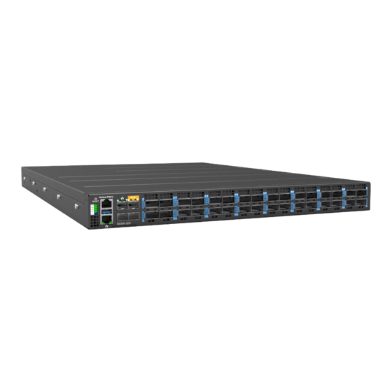
1RU form factor that helps reduce infrastructure and administrative costs. The S9300-32D is the epitome of future networking with a powerful 8-core processor and 32 high-speed 400GE interfaces. It comes with redundant, hot swappable components for convenience, increased availability, reliability and lower costs of maintenance. -
Page 5: Preparation
PC with terminal emulation software. Refer to the "Initial System Setup" section for details. • Baud rate: 115200 bps • Data bits: 8 • Parity: None • Stop bits: 1 • Flow control: None S9300-32D Hardware Installation Guide | 2... -
Page 6: Installation Environment Requirements
Space Clearance: The S9300-32D width is 17.17 inches (43.6cm) and shipped with a rack mount brackets suitable for 19 inch (48.3cm) wide racks. The depth of the S9300-32D chassis is 25.4 inches (64.5cm) without the field replaceable units (FRUs) and comes with adjustable mounting rails suitable for rack depths of 26 inches (66cm) to 30 inches (76.2cm). -
Page 7: Preparation Check List
• Cooling: The S9300-32D has two options for airflow direction. There is a back-to-front option (Figure 3. Left) and a front-to-back option (Figure 3. Right). Make sure the equipment on the same rack have the same airflow direction. (Back-to-Front Airflow) (Front-to-Back Airflow) Figure 3. -
Page 8: Package Contents
Component Physical Information Specification Item Description Total package contents 45.56lbs (20.5kg) Chassis without FRU 23.93lbs (10.77kg) DC PSU: 2.2lbs (1.0kg) Weight DC/AC PSU AC PSU: 2.6lbs (1.2kg) Fan module 0.41lbs (185g) Grounding lug kit 0.147lbs (66.2g) S9300-32D Hardware Installation Guide | 5... - Page 9 0.7lbs (318g) RJ45 to DB9 female cable 0.27lbs (123.9g) 17.17” x 25.4” x 1.72” S9300-32D (W x D x H) (436 x 645 x 43.8mm) Dimension PSU (W x D x H) 1.99” x 12.64” x 1.57” (50.5 x 321 x 40mm) Fan module(W x D x H) 1.98”...
-
Page 10: Identifying Your System
4 Identifying Your System S9300-32D DC Version Overview Figure 5. S9300-32D Hardware Installation Guide | 7... - Page 11 Figure 6. S9300-32D Hardware Installation Guide | 8...
-
Page 12: S9300-32D Ac Version Overview
S9300-32D AC Version Overview Figure 7. S9300-32D Hardware Installation Guide | 9... -
Page 13: Dc Version Psu Overview
PSUs. The picture on the left is the DC PSU with back-to-front airflow and the picture on the right is the DC PSU for front-to-back airflow. (Back-to-Front Airflow PSU) (Front-to-Back Airflow PSU) Figure 9. S9300-32D Hardware Installation Guide | 10... -
Page 14: Ac Version Psu Overview
PSUs. In Figure 12 below, the left is the AC PSU with back-to-front airflow and the picture on the right is the AC PSU for front-to-back airflow. (Back-to-Front Airflow PSU) (Front-to-Back Airflow PSU) Figure 11. S9300-32D Hardware Installation Guide | 11... -
Page 15: Fan Overview
5+1, hot swappable fan field replaceable unit (FRU). There are two types of fans. In Figure 13, the top picture is for fans with back-to-front airflow and the picture on the bottom is for the fans with front-to-back airflow. (Back-to-Front Airflow Fans) (Front-to-Back Airflow Fans) Figure 13. S9300-32D Hardware Installation Guide | 12... -
Page 16: Port Overview
Port Overview Port ID Form Factor Maximum Support Distance Support Speed 0 ~ 31 QSFP-DD 238.01ft (100m) 400GE Figure 14. S9300-32D Hardware Installation Guide | 13... -
Page 17: Rack Mounting
Make sure the captive screw of the inner rail is positioned at the front of the chassis. 2.2 After the attachment pins are secured to the inner rail, lock the inner rail to the chassis using two M4 screws (one on each chassis side). See Figure 16. S9300-32D Hardware Installation Guide | 14... - Page 18 3.2 Once the rear bracket is secured, pull back the clip of the front bracket attach it to the rack. An audible click can be heard when the bracket is secured onto the rack. Figure 18. S9300-32D Hardware Installation Guide | 15...
- Page 19 4.4 Push the blue release tab on each rail to unlock the rails and slide the chassis all the way into the rack. 4.5 Lock the chassis into place by using the captive screw on the front of the inner rail. Figure 19. S9300-32D Hardware Installation Guide | 16...
-
Page 20: Installing Fan Modules
4. Carefully slide the new fan module into the fan bay and gently push until it is flush with the case. 5. Secure the captive screw on the fan module to lock the fan in place. Figure 22. S9300-32D Hardware Installation Guide | 17... -
Page 21: Installing Power Supply Units
1. Locate the release tab on the PSU. Then press and hold down the release tab to unlock the PSU from the power bay. 2. While holding down the release tab, grip the PSU's handle and firmly pull it out of the power bay. Figure 24. S9300-32D Hardware Installation Guide | 18... - Page 22 5. An audible click will be heard when the PSU is installed correctly. The PSU will not go in all the way if it is in the wrong direction. Illustrations are for reference purposes only. Actual PSU position may differ. DC Version Figure 25. AC Version Figure 26. S9300-32D Hardware Installation Guide | 19...
-
Page 23: Grounding The Router
3. Insert the exposed grounding wire all the way into the hole of the grounding lug (provided with package contents). 4. Using a crimping tool, firmly secure the grounding wire to the grounding lug. Figure 27. S9300-32D Hardware Installation Guide | 20... - Page 24 Figure 28. 6. Using 2 M4 screws and 4 washers (provided with the package contents), firmly lock the grounding lug to either of the designated grounding locations on the router. Figure 29. S9300-32D Hardware Installation Guide | 21...
-
Page 25: Connecting Power
Also, please ensure that both PSUs have been properly installed before powering up the equipment, as the S9300-32D is designed to support 1 + 1 power redundancy. 2. Attach the DC power cables to the lugs. - Page 26 (Top picture). Secure the one-hole lug (with the DC power cable attached) to the terminal block (Middle picture). Put plastic cover back on terminal block to guard against contact with terminals (Bottom picture). S9300-32D Hardware Installation Guide | 23...
-
Page 27: Ac Version
Also, please ensure that both PSUs have been properly installed before powering up the equipment, as the S9300-32D is designed to support 1 + 1 power redundancy. 2. Attach the power cable. - Page 28 4. Verify that the power supply is operating. If connected correctly, when turned on, the LED on the PSU will light up with a solid Green color designating normal operation. S9300-32D Hardware Installation Guide | 25...
-
Page 29: Verifying System Operation
PSU0 working normal Blinking Amber PSU0 fail (PSU0 needs service) PSU1 No power Solid Green PSU1 working normal Blinking Amber PSU1 fail (PSU1 needs service) No Power Blinking Blue Beacon feature is enabled on the switch S9300-32D Hardware Installation Guide | 26... -
Page 30: Psu Fru Led
Blinking Green (2/sec) Power supply firmware updating (Boot-loader mode). Fan FRU LED LED Condition Equipment Status No input power Solid Green Fan is functioning normal Solid Amber Fan is abnormal, service is required S9300-32D Hardware Installation Guide | 27... -
Page 31: Initial System Setup
4. Login to the device. After the connection is established, a prompt for the username and password displays. Enter the username and password to access the CLI. The username and password should be provided S9300-32D Hardware Installation Guide | 28... -
Page 32: Cable Connections
There are two types of OOB management ports that can both access the x86 for management purposes. 1. The first port type is the RJ45 OOB port marked a symbol. 2. The second port type is the two 10G SFP+ ports also marked with a symbol. Figure 37. S9300-32D Hardware Installation Guide | 29... - Page 33 3. Place the bail (wire handle) in the unlocked position and align the transceiver with the port. 4. Slide the transceiver into the port and use gentle pressure to secure it in place. An audible click can be heard when the transceiver is secured in the port. S9300-32D Hardware Installation Guide | 30...
- Page 34 The equipment and its modules should only be repaired, maintained or replaced by skilled personnel. Instructed person is a term applied to persons who have been instructed and trained by a skilled person, or who is supervised by a skilled person. S9300-32D Hardware Installation Guide | 31...
- Page 35 www.ufispace.com...
Need help?
Do you have a question about the S9300-32D and is the answer not in the manual?
Questions and answers