Table of Contents
Advertisement
Quick Links
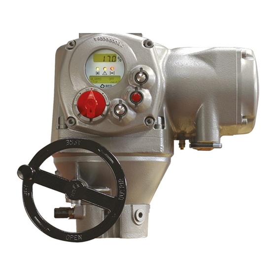
Biffi F01-2000
Electric Actuator
GENERAL INSTRUCTIONS FOR INSTALLATION
OPERATION AND CONFIGURATION
Copyright © Biffi. The information in this document is subject to change without notice. Updated data sheets can be obtained from our website www.biffi.it or from your nearest Biffi Center:
Biffi Italia s.r.l. - Strada Biffi 165, 29017 Fiorenzuola d'Arda (PC) – Italy PH: +39 0523 944 411 – biffi_italia@biffi.it
Installation, Operation and Maintenance Manual
MAINTENANCE AND TROUBLESHOOTING
SPARE PARTS AND DRAWINGS
VCIOM-01249-EN Rev. 0
September 2021
Advertisement
Table of Contents

Related Manuals for BIFFI F01-2000


Summary of Contents for BIFFI F01-2000
- Page 1 SPARE PARTS AND DRAWINGS Copyright © Biffi. The information in this document is subject to change without notice. Updated data sheets can be obtained from our website www.biffi.it or from your nearest Biffi Center: Biffi Italia s.r.l. - Strada Biffi 165, 29017 Fiorenzuola d'Arda (PC) – Italy PH: +39 0523 944 411 – biffi_italia@biffi.it...
- Page 2 Revision Details Installation, Operation and Maintenance Manual September 2021 VCIOM-01249-EN Rev. 0 Revision Details Rev. Date Description Prepared Checked Approved September 2021 General update (Migration to new template) Revision Details...
-
Page 3: Table Of Contents
Installation, Operation and Maintenance Manual Table of Contents VCIOM-01249-EN Rev. 0 September 2021 Table of Contents Section 1: General Safety Instructions Range of Application ..................1 Safety Instructions for Installation in Hazardous Area ........1 1.2.1 Marking ....................2 Applicable Standards and Regulations ............2 Terms and Conditions ................... - Page 4 Output Contacts ................27 5.7.2 ESD Operation .................. 28 5.7.3 Interlock Inputs ................30 Operating the F01-2000 for the First Time ..........30 Optional Modules ..................32 5.9.1 Fieldbus Interface for Remote Control via Fieldbus ......32 5.9.2 Ain/Aout Card .................. 33 5.10...
- Page 5 Installation, Operation and Maintenance Manual Table of Contents VCIOM-01249-EN Rev. 0 September 2021 Valve Data ....................72 9.2.1 Sample Configuration Procedure ............73 Maintenance ....................73 9.3.1 Set Password ..................74 9.3.2 Clear Alarm Log ................74 9.3.3 Set Torque Reference ................ 74 9.3.4 Set Curve Reference .................
- Page 6 Notes Installation, Operation and Maintenance Manual September 2021 VCIOM-01249-EN Rev. 0 This page is intentionally left blank...
-
Page 7: Section 1: General Safety Instructions
Manual are designed for the operation of industrial valves used in heavy industrial, chemical and petrochemical plants. Biffi will not be liable for any possible damage resulting from use in other than the designated applications. Such risk lies entirely with the user. -
Page 8: Marking
Section 1: General Safety Instructions Installation, Operation and Maintenance Manual September 2021 VCIOM-01249-EN Rev. 0 1.2.1 Marking IECEx INE XX.ZZZZ IECEx reference certificate (CoC) XX ATEX ZZZZ ATEX reference certificate 0080 Notified body for ATEX quality assurance (INERIS) Group II (surface industries) Category 2 apparatus Explosive atmospheres caused by gas, mists or vapors Explosive atmospheres caused by gas dusts... -
Page 9: Terms And Conditions
September 2021 Terms and Conditions Biffi guarantees each single product to be free from defects and to conform to current goods specifications. The warranty period is one year from the date of installation by the first user, or eighteen months from the date of shipment to the first user, whichever occurs first. -
Page 10: Section 2: Storage And Pre-Installation
Section 2: Storage and Pre-Installation Installation, Operation and Maintenance Manual September 2021 VCIOM-01249-EN Rev. 0 Section 2: Storage and Pre-Installation Tests to be Carried Out When the Actuator is Received If the actuator is received already mounted on the valve, all operations should have already been performed during valve/actuator assembly. -
Page 11: General
Biffi actuators are weatherproof to IP68 for a submersion at depth of 15 meters for 90 hours. This condition can only be maintained if the units are correctly installed/ connected on site and if they have been correctly stored. - Page 12 Section 2: Storage and Pre-Installation Installation, Operation and Maintenance Manual September 2021 VCIOM-01249-EN Rev. 0 Figure 2 Figure 3 Figure 4 Storage and Pre-Installation...
-
Page 13: Checks To Be Performed Before Installation
Installation, Operation and Maintenance Manual Section 2: Storage and Pre-Installation VCIOM-01249-EN Rev. 0 September 2021 Figure 5 Figure 6 Checks to be Performed Before Installation • Make sure the valve to be motorised is the appropriate one for coupling to the actuator. -
Page 14: Section 3: Installation
Section 3: Installation Installation, Operation and Maintenance Manual September 2021 VCIOM-01249-EN Rev. 0 Section 3: Installation Working Condition The standard actuators are suitable for the following environment temperatures: -30 °C +85 °C (-22 °F to +185 °F). Special versions are available for extreme environment temperatures: •... - Page 15 Installation, Operation and Maintenance Manual Section 3: Installation VCIOM-01249-EN Rev. 0 September 2021 Figure 8 Figure 9 Installation...
-
Page 16: Manual Operation
Section 3: Installation Installation, Operation and Maintenance Manual September 2021 VCIOM-01249-EN Rev. 0 Figure 10 Manual Operation To manually operate the actuator, it is sufficient to turn the handwheel in the desired direction. WARNING Do not manually operate the actuator with devices other than the handwheel. Using cheater bars, wheel wrenches, pipe wrenches, or other such devices on the actuator handwheel may cause serious personal injury and/or damage to the actuator or valve. -
Page 17: Mounting The Actuator Onto The Valve
ASTM A 320 Grade L7 (or L7M) for studs bolts • ASTM A 194 Grade 4 for nuts WARNING Never lift the valve/actuator assembly without securing slings to both the valve and the actuator. Table 3. Size (DN) Max. weight (kg) F01-2000/150 F01-2000/300 F01-2000/600 Installation... -
Page 18: Electrical Connections
All the accessories (in particular cable glands) must be certified according to 94/9/EC Directive. 3.5.1 Identification of Entries Electric actuators series F01-2000 are equipped with 4 entries (3 are standard the fourth is supplied when requested). With reference to Figure 12, the thread form/size for entry is as follows: Figure 12 Table 5. -
Page 19: Plants Requirements
Installation, Operation and Maintenance Manual Section 3: Installation VCIOM-01249-EN Rev. 0 September 2021 3.5.2 Plants Requirements Protection devices (overcurrent breakers, magneto-thermal switches or fuses) should be provided on the plant at Customer care, to protect the mains line in case of motor overcurrent or loss of insulation between phases and earth. -
Page 20: Cable Entries
Section 3: Installation Installation, Operation and Maintenance Manual September 2021 VCIOM-01249-EN Rev. 0 Cable Entries The sealing of cables and conduit entries should be carried out in accordance with National Standards or the Regulatory Authorities that have certified the actuators. This is particularly true for units that are certified for use in hazardous areas where the method of sealing must be to an approved standard, and cable glands, reducers, plugs and adapters must be approved and separately certified. -
Page 21: Terminal Board
NOTICE The removal of any other covers without Biffi’s approval will invalidate the warranty. Biffi will not accept any responsibility for any damage or deterioration that may occur as a result of cover removal. Terminate the ground connections to the ground stud marked one internal and one external ground studs are provided. - Page 22 Section 3: Installation Installation, Operation and Maintenance Manual September 2021 VCIOM-01249-EN Rev. 0 Figure 15 Figure 16 Installation...
- Page 23 Installation, Operation and Maintenance Manual Section 3: Installation VCIOM-01249-EN Rev. 0 September 2021 Connections for Ex e terminals enclosure The wires must be terminated in accordance with the following method (see connection in Table 6): Table 6. Connection Table Power cables Control cables Type of terminal Insulated ring tongue...
-
Page 24: Instructions For The Explosionproof Enclosures
Instructions for the Explosionproof Enclosures NOTICE Electric actuator F01-2000 shall be installed and maintained according to the applicable rules regarding the electrical installations in hazardous area (other than mines) classified as zone 1 (gas); example: EN 60079-10 (hazardous area classification), EN 60079-14 (electrical installation), EN 60079-17 (maintenance), and/or other national standards. -
Page 25: Installation In Environment With Explosive Dusts
Installation in Environment with Explosive Dusts NOTICE Electric actuator F01-2000 shall be installed and maintained according to the applicable rules regarding the electrical installations in hazardous area (other than mines) classified as zone 21 (dust); example: EN 61241-14 (dust) and/or other national standards. -
Page 26: Section 4: Lubrication
Installation, Operation and Maintenance Manual Section 4: Lubrication September 2021 VCIOM-01249-EN Rev. 0 Section 4: Lubrication Lubrication Inspection The actuator is lubricated for life, therefore under normal working conditions it is not necessary to replace or refill the oil. However it is recommended to check the oil level every 3-5 years using holes 1 or 2 depending on mounting position. -
Page 27: Section 5: Operating The F01-2000
Installation, Operation and Maintenance Manual Section 5: Operating the F01-2000 VCIOM-01249-EN Rev. 0 September 2021 Section 5: Operating the F01-2000 Operation by Handwheel To manually operate the actuator, it is sufficient to turn the handwheel in the desired direction. The manual operation is always possible without any clutching mechanism. -
Page 28: Setting Of Mechanical Stops
Section 5: Operating the F01-2000 Installation, Operation and Maintenance Manual September 2021 VCIOM-01249-EN Rev. 0 Setting of Mechanical Stops Necessary equipment: a 3 mm hexagonal key. According to the type of valve to be operated, the actuator can be stopped by means of... - Page 29 Installation, Operation and Maintenance Manual Section 5: Operating the F01-2000 VCIOM-01249-EN Rev. 0 September 2021 Hold the lock nut and remove the mechanical stop protection by unscrewing it. Remove the seal washer. Figure 21 Hold the mechanical stop by means of a suitable Allen key and in the same time loosen the lock nut by one turn.
-
Page 30: Electrical Operation
Section 5: Operating the F01-2000 Installation, Operation and Maintenance Manual September 2021 VCIOM-01249-EN Rev. 0 Electrical Operation Before connecting power to the actuator, check that the voltage is correct and according to the indications on the nameplate. Wrong power supply could cause a permanent damage to the electrical components. -
Page 31: Local Indication
Installation, Operation and Maintenance Manual Section 5: Operating the F01-2000 VCIOM-01249-EN Rev. 0 September 2021 Figure 24 OPEN/YES STOP CLOSE/NO Local Indication The upper display (3 1/2 LCD) indicates the valve position as a percentage of opening (open = 100%). -
Page 32: Remote Control
Section 5: Operating the F01-2000 Installation, Operation and Maintenance Manual September 2021 VCIOM-01249-EN Rev. 0 Lock of the 3-Position Selector The 3-position selector can be locked in any of its three positions by means of a padlock. Figure 26 Remote Control Place the 3-position selector in REMOTE to transfer the actuator control to a remote device. -
Page 33: Output Contacts
Installation, Operation and Maintenance Manual Section 5: Operating the F01-2000 VCIOM-01249-EN Rev. 0 September 2021 2 WIRES (see the remote connections diagram) With the “2 wires” option 2 different activities may be selected: In “2 wires, signal ON to open”, the actuator opens if the signal switches to ON and closes if the signal goes to OFF. -
Page 34: Esd Operation
Section 5: Operating the F01-2000 Installation, Operation and Maintenance Manual September 2021 VCIOM-01249-EN Rev. 0 5.7.3 ESD Operation An ESD (Emergency Shut Down) signal can be sent to the actuator to override any existing command and to drive the valve to a predetermined position. - Page 35 Installation, Operation and Maintenance Manual Section 5: Operating the F01-2000 VCIOM-01249-EN Rev. 0 September 2021 Figure 27 OPTION A1 OPTION B1 OPTION A2 OPTION B2 OPTION A3 OPTION B3 Operating the F01-2000...
-
Page 36: Interlock Inputs
Total current drawn from remote controls < 20 mA. Operating the F01-2000 for the First Time Before attempting to operate the F01-2000 for the first time, check that the actuator is correctly mounted on the valve. Place the 3-position selector in OFF and switch the power on. - Page 37 (see Section 12.10). If the upper line of the display shows “WARNING OFF”, a warning condition is present. You can go ahead since the F01-2000 is working well, but some datum is not according to the configured parameters (see Section 12.10).
-
Page 38: Optional Modules
• Modbus RTU A Hardware alarm is generated if the F01-2000 was set to be equipped with bus card, but the card is damaged or missing. A BUS REPORT is also present in the list of reports if the card is present (see Section 6). See the specific manuals for instructions and the setting of the above modules. -
Page 39: Ain/Aout Card
5.9.2 Ain/Aout Card With the above card the F01-2000 is provided with a 4 - 20 mA analog input and a 4 - 20 mA analog output. This card should be plugged on the base card, replacing the “TERMINAL BOARD ADAPTOR” card supplied as standard. A Hardware alarm is generated if the F01-2000 was set to be equipped with an Ain/Aout card, and the card is damaged or missing. - Page 40 VCIOM-01249-EN Rev. 0 4 - 20 mA analog input The 4 - 20 mA analog input is the position request R% signal and is used by the F01-2000 to position the valve in inching and modulating actuators. The “POSITIONER” routine...
-
Page 41: Base Card Of The F01-2000 V4
Installation, Operation and Maintenance Manual Section 5: Operating the F01-2000 VCIOM-01249-EN Rev. 0 September 2021 5.10 Base Card of the F01-2000 V4 Figure 32 Bottom view of base card Terminal Board Adaptor card (TBA) Top view of base card Base card equipped with fieldbus interface card and Terminal Board Adaptor card. - Page 42 Section 5: Operating the F01-2000 Installation, Operation and Maintenance Manual September 2021 VCIOM-01249-EN Rev. 0 Fieldbus interface card The type of card depends on the fieldbus present in the plant. Figure 34 Fieldbus interface card Figure 35 Bluetooth™ Operating the F01-2000...
- Page 43 This optional card is used in place of the Terminal Board Adaptor (TBA) card when an analog 4 - 20 mA input and output signal is requested. This card cannot be used in the actuators with terminal board series F01-2000 v0 (see Section 5.8, Operating the F01-2000 for the first time).
-
Page 44: Section 6: Local Controls
Section 6: Local Controls Installation, Operation and Maintenance Manual September 2021 VCIOM-01249-EN Rev. 0 Section 6: Local Controls Description of the Local Operator Interface The following functions are available by the F01-2000 local operator interface: • actuator control • actuator configuration •... - Page 45 — REMOTE: for remote control only The F01-2000 can be provided with a radiofrequency wireless connection based on a qualified Bluetooth™ class 1 module. This allows to establish a connection and exchange data with a PDA or PC with built-in Bluetooth™ technology. The following tasks can be wirelessly performed: —...
- Page 46 Section 6: Local Controls Installation, Operation and Maintenance Manual September 2021 VCIOM-01249-EN Rev. 0 Three LED’s to indicate the actuator status according to the following logic: — green ON/ red OFF: the actuator is stopped in open position — green OFF/ red ON: the actuator is stopped in closed position —...
- Page 47 Installation, Operation and Maintenance Manual Section 6: Local Controls VCIOM-01249-EN Rev. 0 September 2021 Description of Variables and Reports torque output torque in % of the nominal torque stated in the NAMEPLATE menu motor speed RPM of electrical motor main voltage voltage (V) and frequency (Hz) of mains current current (A) absorbed by the motor...
- Page 48 Section 6: Local Controls Installation, Operation and Maintenance Manual September 2021 VCIOM-01249-EN Rev. 0 The Figure 39 shows the use of the OPEN / YES, CLOSE / NO and STOP pushbuttons in function of the local selector position. Figure 39 LOCAL REMOTE 3-POSITION SELECTOR...
-
Page 49: Configuration Options
September 2021 Configuration Options The F01-2000 actuator can be totally configured from the local interface by means of a series of menus that can be selected from the alphanumeric display. The operator is guided through the different displays by answering YES or NO to the appropriate prompt (change? OK?, view?, next?, etc.) in the right corner of the lower row of the alphanumeric display. - Page 50 Section 6: Local Controls Installation, Operation and Maintenance Manual September 2021 VCIOM-01249-EN Rev. 0 Nameplate This menu includes a series of data identifying the actuator characteristics, service, and utilization mode. The data are entered by the manufacturer and can only be viewed (i.e., this menu is only available in View mode).
-
Page 51: Entering The View Mode
Installation, Operation and Maintenance Manual Section 6: Local Controls VCIOM-01249-EN Rev. 0 September 2021 Maintenance This menu includes all diagnostic and historic data which can help the operator in case of failure or during maintenance operations. The Maintenance menu also includes the “Set password”... -
Page 52: Entering The Set-Up Mode
All settings are automatically saved to a non-volatile memory and retained also if the electrical power is removed from the actuator. All F01-2000 actuators are configured before shipping with a standard default setting unless alternatives were requested on order. - Page 53 Installation, Operation and Maintenance Manual Section 6: Local Controls VCIOM-01249-EN Rev. 0 September 2021 Figure 40 shows the procedure to enter view and set-up mode. Figure 40 Local Controls...
-
Page 54: Section 7: Set-Up Menu
Section 7: Set-Up Menu Installation, Operation and Maintenance Manual September 2021 VCIOM-01249-EN Rev. 0 Section 7: Set-Up Menu Figure 41 Set-Up Menu... - Page 55 Installation, Operation and Maintenance Manual Section 7: Set-Up Menu VCIOM-01249-EN Rev. 0 September 2021 The Figure 42 shows the procedure to move in the set-up routines. Figure 42 Set-Up Menu...
-
Page 56: Section 8: View Menu
Installation, Operation and Maintenance Manual Section 8: View Menu September 2021 VCIOM-01249-EN Rev. 0 Section 8: View Menu Figure 43 View Menu... - Page 57 Installation, Operation and Maintenance Manual Section 8: View Menu VCIOM-01249-EN Rev. 0 September 2021 The Figure 44 shows the procedure to move in the view routines. Figure 44 View Menu...
-
Page 58: Section 9: Set-Up Routines
Section 9: Set-Up Routines Installation, Operation and Maintenance Manual September 2021 VCIOM-01249-EN Rev. 0 Section 9: Set-Up Routines Actuator Set-Up 9.1.1 Set Stroke Limits This routine allows the actuator to be configured according to the type of valve it is mounted on. - Page 59 Installation, Operation and Maintenance Manual Section 9: Set-Up Routines VCIOM-01249-EN Rev. 0 September 2021 Close limit by position • Move the local selector to LOCAL. The local controls can be used. • Move the valve to closed position (by CLOSE control or by handwheel). •...
-
Page 60: Torque Set-Up
Section 9: Set-Up Routines Installation, Operation and Maintenance Manual September 2021 VCIOM-01249-EN Rev. 0 9.1.2 Torque Set-Up The output torque limits to close or to open may be configured between 40% and 100% of the nominal torque stated on the actuator nameplate. Set-up procedure •... - Page 61 Installation, Operation and Maintenance Manual Section 9: Set-Up Routines VCIOM-01249-EN Rev. 0 September 2021 Configuration procedure • Move the local selector to OFF and then simultaneously press OPEN and STOP. Select the language and then enter the password according to the instructions (see “Entering the set-up mode”).
-
Page 62: Remote Controls
Section 9: Set-Up Routines Installation, Operation and Maintenance Manual September 2021 VCIOM-01249-EN Rev. 0 9.1.4 Remote Controls The actuator may be remotely controlled by 4, or 3, or 2 wires depending on the connection made on the terminal board of the actuator. The following options are available: •... -
Page 63: Output Relays
Installation, Operation and Maintenance Manual Section 9: Set-Up Routines VCIOM-01249-EN Rev. 0 September 2021 Configuration procedure • Move the local selector to OFF and then simultaneously press OPEN and STOP. Select the language and then enter the password according to the instructions (see “Entering the set-up mode”). - Page 64 Section 9: Set-Up Routines Installation, Operation and Maintenance Manual September 2021 VCIOM-01249-EN Rev. 0 The following situation can be configured individually to switch-over the monitor relay: • motor over-temperature • over-torque • jammed valve • LOCAL/OFF selected • manual operation •...
- Page 65 September 2021 The contacts may be configured to make or break on condition. The options “EFS in manual”, “EFS mid-travel” and “PST failed” also appear in the menu but are not available for F01-2000 v4. Configuration procedure • Move the local selector to OFF and then simultaneously press OPEN and STOP.
- Page 66 Section 9: Set-Up Routines Installation, Operation and Maintenance Manual September 2021 VCIOM-01249-EN Rev. 0 Default #2 Monitor relay • main voltage failure • lost phase • local/off selected • local stop pressed • manual operation • internal temperature alarm • K1 contactor failure •...
-
Page 67: Positioner
The “position request R%” signal may either be received from the bus or the 4 - 20 mA analog input. If the F01-2000 is set to receive the position request R% from the bus, a fieldbus interface card must be present, or a Hardware alarm will be generated. If the F01-2000 is set to receive the position request R% from the 4 - 20 mA generator, the Ain/Aout card must be present, or a Hardware alarm will be generated. - Page 68 Section 9: Set-Up Routines Installation, Operation and Maintenance Manual September 2021 VCIOM-01249-EN Rev. 0 Figure 45 INPUT 4 - 20 mA INPUT 4 - 20 mA POLARITY: 4 mA = CL POLARITY: 4 mA = OP Input request Input request 20 mA 20 mA 4 mA...
- Page 69 Installation, Operation and Maintenance Manual Section 9: Set-Up Routines VCIOM-01249-EN Rev. 0 September 2021 Figure 46 EXAMPLE B EXAMPLE A Position request % Position request % 100% Configured values: Configured values: 100% % min = 0% % min = 25% % max = 100% % max = 75% Polarity : 4 mA = CL...
-
Page 70: Fail-Safe
This action only takes place if the local selector is in REMOTE and if the positioning function or the bus interface are active. When the 4 - 20 mA or bus signal is restored, the F01-2000 resumes its normal functioning. The Interlock and ESD controls override the fail-safe action according to Figure 47. -
Page 71: Out 4 - 20 Ma
9.1.9 Out 4 - 20 mA This routine is only available if the Ain/Aout card is present. With this card the F01-2000 is provided with a 4 - 20 mA analog input and a 4 - 20 mA analog output. -
Page 72: Interlock
Section 9: Set-Up Routines Installation, Operation and Maintenance Manual September 2021 VCIOM-01249-EN Rev. 0 9.1.10 Interlock The interlock inputs can be used to inhibit the actuator movement in open or close direction. The controls are momentary, the inhibit action continues until the relevant signal is present. - Page 73 Installation, Operation and Maintenance Manual Section 9: Set-Up Routines VCIOM-01249-EN Rev. 0 September 2021 Closing direction • Press YES if the status is OK, or NO to change. Press YES to confirm (status = On, enables 2-speed timer operation in closing direction status = Off, disables timer operation in closing direction).
-
Page 74: Bus (Or Fdi Control)
(node address, termination, etc.) necessary to connect the actuator to a fieldbus. If the F01-2000 was set to work with fieldbus, but the fieldbus card is not present, a Hardware alarm will be generated. Different interfaces are available to connect the F01-2000 to different types of fieldbus. - Page 75 Installation, Operation and Maintenance Manual Section 9: Set-Up Routines VCIOM-01249-EN Rev. 0 September 2021 9.1.13.2 Factory Settings The above routine resets the present configuration and restores the default configuration as below: Table 11. Stroke limits Close direction: CW Close limit: by position Open limit: by position Torque set-up Closing torque: 40%...
- Page 76 Section 9: Set-Up Routines Installation, Operation and Maintenance Manual September 2021 VCIOM-01249-EN Rev. 0 9.1.13.3 Torque Limits Torque limits are used as a reference for torque alarm and end of travel. With the option “standard”, the torque limits are constant along the full stroke. The limits can be configured in the “stroke limits”...
- Page 77 Installation, Operation and Maintenance Manual Section 9: Set-Up Routines VCIOM-01249-EN Rev. 0 September 2021 9.1.13.4 Lithium Battery On request, the actuator can be provided with a lithium battery to update the remote outputs (output relays status and bus messages) in case of electrical power failure and manual override operations.
-
Page 78: Valve Data
Section 9: Set-Up Routines Installation, Operation and Maintenance Manual September 2021 VCIOM-01249-EN Rev. 0 9.1.13.6 Valve Jammed (Time) The valve jammed time is used to monitor the following situations: The time passed after receiving an open or close control is greater than the “valve jammed time”, but the valve position variation is smaller than 0.5%. -
Page 79: Sample Configuration Procedure
Installation, Operation and Maintenance Manual Section 9: Set-Up Routines VCIOM-01249-EN Rev. 0 September 2021 9.2.1 Sample Configuration Procedure Tag name • Move the local selector to OFF and then simultaneously press OPEN and STOP. Select the language and enter the password according to the instructions (see “Entering the set-up mode”). -
Page 80: Set Password
9.3.1 Set Password The actuator is supplied by Biffi with a default password (“0 0 0 0”). By the above routine, the end user can enter a different password consisting of 4 alphanumeric characters. After entering the new password, the old one ceases to be valid. Therefore, it is mandatory “NOT TO FORGET THE PASSWORD”... -
Page 81: Set Curve Reference
The “set curve reference” routine allows to select 1 off 100 opening and closing torque curves in the memory of the F01-2000 and to transfer them to the torque curve reference registers. The old reference data are lost, and the new ones will be the new torque curves reference (see VIEW mode, Maintenance, Torque curve, Section 10.4.3). -
Page 82: Set Maintenance Date
Section 9: Set-Up Routines Installation, Operation and Maintenance Manual September 2021 VCIOM-01249-EN Rev. 0 9.3.6 Set Maintenance Date The maintenance date routine allows the following operations: • to set the last maintenance date • to set the next maintenance date •... -
Page 83: Set Data Logger
Installation, Operation and Maintenance Manual Section 9: Set-Up Routines VCIOM-01249-EN Rev. 0 September 2021 9.3.7 Set Data Logger The “data logger” routine allows to set the data logger parameters (see VIEW mode, Maintenance, Data logger, Section 10.4.6). To start the data logger, the following data should be set: Logger mode recorder, event, off... -
Page 84: Example Of Set-Up Routine
Section 9: Set-Up Routines Installation, Operation and Maintenance Manual September 2021 VCIOM-01249-EN Rev. 0 Example of Set-Up Routine 9.4.1 Torque Set-up Figure 51 LOCAL REMOTE TORQUE SETUP SETUP MODE ACTUATOR SETUP STROKE LIMIT CHANGE? CHANGE? CHANGE? 3-POSITION SELECTOR DISPLAY XXXXXX CLOSING TORQUE OPENING TORQUE STOP... -
Page 85: Section 10: View Routines
Installation, Operation and Maintenance Manual Section 10: View Routines VCIOM-01249-EN Rev. 0 September 2021 Section 10: View Routines 10.1 Actuator Set-Up The above menu allows to view the present actuator configuration. No change can be made to the present data. The following data can be viewed (see Table 12). Table 12. -
Page 86: Nameplate
Icc, max 999.9 A — Duty (S2/15 min, etc.) — Poles (2, 4, etc.) — Biffi name, max. 28 characters — Gear ratio, max. 1000 • Test date: date of the in-house functional test of actuator. • Wiring diagram (WD): wiring diagram number, max 28 characters. -
Page 87: Valve Data
Installation, Operation and Maintenance Manual Section 10: View Routines VCIOM-01249-EN Rev. 0 September 2021 10.3 Valve Data To identify the valve and its function in the process, the following data can be viewed: • Tag name (max. 28 characters) • Serial number (max. -
Page 88: Torque Profile
Details are given of the reference and latest torque expressed in % of the nominal torque. At the end of a full stroke in opening or closing, the F01-2000 stores the 3 maximum torque values in position intervals 0%-10%, 10%-90%, 90%-100% in opening, and the 3 maximum torque values in position intervals 100%-90%, 90%-10%, 10%-0% in closing. -
Page 89: Torque Curve
1% of position variation. At the end of the stroke the collected 101 values (one torque value every 1% of position change) are saved in the F01-2000 memory together with the time and date of strokes, main voltage, motor temperature, temperature inside the electronics compartment and temperature inside the terminal board compartment. -
Page 90: Operation Log
Installation, Operation and Maintenance Manual Section 10: View Routines September 2021 VCIOM-01249-EN Rev. 0 The amount of data to be viewed is large and the local display can only visualize one datum at a time. To use this function, we suggest to utilize the features available with PDA’s and PC through Bluetooth™... - Page 91 Installation, Operation and Maintenance Manual Section 10: View Routines VCIOM-01249-EN Rev. 0 September 2021 Figure 52 Reference torque curve Latest torque curve Table 14 shows list of data collected by the general and recent data log. Table 14. Routine Parameters Opening time Closing time Contactor cycles...
- Page 92 Installation, Operation and Maintenance Manual Section 10: View Routines September 2021 VCIOM-01249-EN Rev. 0 View procedure • Move the local selector to OFF and then simultaneously press OPEN and STOP. Select the language according to the instructions (see “Entering the view mode”). When the message displayed is “VIEW MODE OK?”...
-
Page 93: Maintenance Date
Since the amount of collected data is very large, the data logger can only be viewed by means of a PDA or PC. The data can be up-loaded from F01-2000 to PDA or PC by the BluetoothTM wireless connection. - Page 94 September 2021 VCIOM-01249-EN Rev. 0 Data logger modes: • OFF: the data logger is not active. • RECORDER mode: the F01-2000 measures and memorizes the following 3 data: — Main voltage supply (V) — Motor temperature (°C) — Temperature inside the compartment of electronics (°C) •...
- Page 95 Torque limit in CL is set to 90%, torque limit in OP is set to 100%. Blue graph shows Torque OP versus time, yellow graph shows Torque CL versus time. The data remain in the F01-2000 v4 permanent memory until a new start of data logger is set. Figure 54...
- Page 96 VCIOM-01249-EN Rev. 0 • EVENT mode: the F01-2000 detects the type of received command (OPEN or CLOSE), the source of the command (local controls, remote controls, bus, etc.) and date and time of command. Up to 128 EVENTS can be memorized. As the memory is full, the logger stops to memorize events or overwrites the previous data according to the selected MEMORY MODE (“stop when full”...
-
Page 97: Example Of View Routine
Installation, Operation and Maintenance Manual Section 10: View Routines VCIOM-01249-EN Rev. 0 September 2021 10.5 Example of View Routine 10.5.1 View Torque Set-Up Figure 56 LOCAL REMOTE TORQUE SETUP VIEW MODE ACTUATOR SETUP STROKE LIMIT VIEW? VIEW? VIEW? 3-POSITION SELECTOR DISPLAY CLOSING TORQUE XXXXXX... -
Page 98: Section 11: Maintenance
Standard Maintenance Approx. every 2 years: Under normal operating conditions, the F01-2000 is maintenance-free: no actuator maintenance is formally required, even though visual inspection for oil leakage or external visible damages is recommended every two years. When conditions are severe (frequent operation or high temperatures), inspect the oil level and oil quality more often. -
Page 99: Special Maintenance
11.2 Special Maintenance In case actuator failure, please refer to Section 12, Troubleshooting for possible causes. Spare parts can be required to Biffi: please refer to the individual item number shown in Section 13, Parts list and drawings. NOTICE Special maintenance is also recommended when, during operations, the actuator generates an excessive noise. -
Page 100: Lithium Battery Change
Installation, Operation and Maintenance Manual Section 11: Maintenance September 2021 VCIOM-01249-EN Rev. 0 11.3 Lithium Battery Change Figure 57 • Isolate the main supply to the actuator and all other control voltages. • Open the terminal boards cover. • Disconnect two wires (+) (-) from the main board. •... - Page 101 Installation, Operation and Maintenance Manual Section 11: Maintenance VCIOM-01249-EN Rev. 0 September 2021 Figure 60 — Remove the battery cover. Figure 61 Figure 62 View Routines...
- Page 102 Installation, Operation and Maintenance Manual Section 11: Maintenance September 2021 VCIOM-01249-EN Rev. 0 Figure 63 — Replace the battery. Figure 64 Figure 65 View Routines...
- Page 103 Installation, Operation and Maintenance Manual Section 11: Maintenance VCIOM-01249-EN Rev. 0 September 2021 Figure 66 WARNING If the actuator is located in a hazardous area a “hot work” permit must be obtained unless the actuator can be moved to a non-hazardous area. NOTICE The new battery must be the same type as the one provided: Lithium –...
-
Page 104: Section 12: Troubleshooting
September 2021 VCIOM-01249-EN Rev. 0 Section 12: Troubleshooting The F01-2000 actuator has passed the functional test performed by Biffi Quality Assurance personnel. WARNING The actuator is non-intrusive. The control compartment was sealed in dry and clean conditions and contains no site serviceable components. Do not open it unless absolutely necessary. -
Page 105: Dc Output Voltage Not Available At The Terminals
Installation, Operation and Maintenance Manual Section 12: Troubleshooting VCIOM-01249-EN Rev. 0 September 2021 12.2 DC Output Voltage Not Available at the Terminals • Switch the main power supply off and disconnect all wires from terminals B1-B2 and C1. • Switch the main power supply on and check if the voltage on the terminals B1-B2 and C1 is between 23 and 27 V DC. -
Page 106: The Motor Is Very Hot And Does Not Start
Section 12: Troubleshooting Installation, Operation and Maintenance Manual September 2021 VCIOM-01249-EN Rev. 0 12.4 The Motor Is Very Hot and Does Not Start • Check that no alarm other than motor overheating is present. • Wait until the motor cools down and the normally closed contact of the thermal switch automatically resets before trying to operate the actuator again. -
Page 107: The Actuator Does Not Stop In Fully Open Or Fully Closed Position
Installation, Operation and Maintenance Manual Section 12: Troubleshooting VCIOM-01249-EN Rev. 0 September 2021 12.8 The Actuator Does Not Stop in Fully Open or Fully Closed Position • Check that the actual open and close positions of the valve respectively correspond to 100% and 0% on the actuator display. •... - Page 108 Section 12: Troubleshooting Installation, Operation and Maintenance Manual September 2021 VCIOM-01249-EN Rev. 0 Figure 68 LOCAL REMOTE WARNINGS ALARMS VIEW? VIEW? 3-POSITION SELECTOR DISPLAY XXXXXX WARNING II- 1 ALARM II- I XXXXXX NEXT? NEXT? XXXXXX NEXT? VIEW VARIABLES WARNING II- N ALARM II- N NEXT? NEXT?
- Page 109 Installation, Operation and Maintenance Manual Section 12: Troubleshooting VCIOM-01249-EN Rev. 0 September 2021 Table 17. Alarm Table Available controls Display Condition for alarm Action Local Remote Alarm reset message High torque Measured torque greater Operate the actuator Only Only open Configuration Close control in closing...
- Page 110 Section 12: Troubleshooting Installation, Operation and Maintenance Manual September 2021 VCIOM-01249-EN Rev. 0 Available controls Display Condition for alarm Action Local Remote Alarm reset message Configuration The checksum of the Reconfigure all Not available Not available Memory OK error EEPROM memory that parameters available contains the configuration...
-
Page 111: Section 13: Parts List And Drawings
Section 13: Parts List and Drawings 13.1 Introduction This chapter includes the drawings and parts list of each component and subassembly of F01-2000 actuators. NOTICE • When ordering spare parts, please indicate the serial number embossed on the actuator nameplate. - Page 112 Section 13: Parts List and Drawings Installation, Operation and Maintenance Manual September 2021 VCIOM-01249-EN Rev. 0 Table 19. Parts List Item Description Item Description Item Description Screw Worm wheel Column Terminal board cover Planicentric assembly Torque plate * O-ring Guide bush Screw Terminals label * O-ring...
- Page 113 Installation, Operation and Maintenance Manual Section 13: Parts List and Drawings VCIOM-01249-EN Rev. 0 September 2021 Figure 70 F01-2000 - Planicentric Assembly 30.1 30.2 30.3 30.4 30.5 30.4 30.2 30.3 30.2 30.6 30.7 30.8 Table 20. Parts List Item Description 30.1...
- Page 114 Section 13: Parts List and Drawings Installation, Operation and Maintenance Manual September 2021 VCIOM-01249-EN Rev. 0 Figure 71 F01-2000 - Worm Gear Assembly 49.7 49.6 49.5 49.4 49.3 49.2 49.1 Table 21. Parts List Item Description 49.1 Stop ring 49.2 Spring support 49.3...
- Page 115 Installation, Operation and Maintenance Manual Section 13: Parts List and Drawings VCIOM-01249-EN Rev. 0 September 2021 Figure 72 F01-2000 - Torque/Position Assembly 61.1 61.3 61.5 61.7 61.9 61.11 61.13 61.2 61.4 61.6 61.8 61.10 61.12 Table 22. Parts List Item Description 61.1...
- Page 116 Section 13: Parts List and Drawings Installation, Operation and Maintenance Manual September 2021 VCIOM-01249-EN Rev. 0 Figure 73 F01-2000 - Local Interface Assembly 72.6 72.5 72.4 72.3 72.2 72.1 Table 23. Parts List Item Description 72.1 Plug 72.2 * Screw 72.3...
- Page 117 Installation, Operation and Maintenance Manual Notes VCIOM-01249-EN Rev. 0 September 2021 This page is intentionally left blank...
- Page 118 VCIOM-01249-EN ©2021 Biffi. All rights reserved. Biffi Italia s.r.l. Strada Biffi 165 The contents of this publication are presented for information purposes only, 29017 Fiorenzuola d’Arda (PC) and while every effort has been made to ensure their accuracy, they are not...
Need help?
Do you have a question about the F01-2000 and is the answer not in the manual?
Questions and answers