Table of Contents
Advertisement
Quick Links
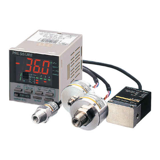
Pressure Sensor
E8MS/E8M
Four-channel Input Controller for
Control of Multiple Sensor Heads
Be sure to read Safety Precautions on
page 12.
Ordering Information
Sensors
E8MS
Positive pressure
Negative pressure
Compound pressure
* Do not connect the E8MS-N1 to a Controller. A Controller is not necessary.
E8M
Minute pressure
differential
Positive pressure
Negative pressure
Controllers
Power supply voltage
24 VDC
* The E8M-MP8 cannot be connected to the E8MS-N1.
Arrow.com.
Downloaded from
Pressure range
0 to 100 kPa
0 to 1 MPa
0 to −101 kPa
−101 to 101 kPa
Pressure range
Differential pressure from 0 to 1,000 Pa
between positive and negative ports
0 to 1 MPa
0 to −101 kPa
Output configuration
NPN open collector
CSM_E8MS_E8M_DS_E_3_1
Output configuration
E8MS-01
E8MS-10
Linear output: 1 to 5 V
E8MS-N0
E8MS-N1
Output configuration
E8M-A1-S
Linear output: 1 to 5 V
E8M-10
E8M-N0
Number of sensor inputs
4
K3C-MP8
CH
Model
*
Model
Models
*
1
Advertisement
Table of Contents

Related Manuals for Omron E8MS Series


Summary of Contents for Omron E8MS Series
- Page 1 Pressure Sensor E8MS/E8M CSM_E8MS_E8M_DS_E_3_1 Four-channel Input Controller for Control of Multiple Sensor Heads Be sure to read Safety Precautions on page 12. Ordering Information Sensors E8MS Pressure range Output configuration Model 0 to 100 kPa E8MS-01 Positive pressure 0 to 1 MPa E8MS-10 Linear output: 1 to 5 V 0 to −101 kPa...
- Page 2 E8MS/E8M Accessories (Order Separately) Sensor I/O Connectors Applicable model Appearance Model Specifications Unit Remarks 4-pin connector with E89-M3-S 3-m-long cable Provided with one XN2A-1430 e-CON Con- nector for Cable Connection. 3-pin connector with E8MS E89-M4-S 3-m-long cable 3-conductor, 3-m-long E8MS/E80-C2 E89-M4-1 cable with connectors Cannot be cut or extended.
-
Page 3: Ratings And Specifications
E8MS/E8M Ratings and Specifications Sensors E8MS Item Model E8MS-01 E8MS-10 E8MS-N0 E8MS-N1 Power supply voltage 12 VDC ±10%, ripple (p-p) of 5% max. Current consumption 25 mA max. Pressure type Gauge pressure Applicable fluid Non-corrosive gas and non-flammable gas 0 to −101 kPa −101 to 100 kPa Rated pressure range 0 to 100 kPa... - Page 4 E8MS/E8M Item Model E8M-A1-S E8M-10 E8M-N0 Power supply voltage 12 VDC ±10%, ripple (p-p) of 5% max. Current consumption 30 mA max. Pressure type Differential pressure Gauge pressure Applicable fluid Non-corrosive gas and non-flammable gas Differential pressure from 0 to 0 to −101 kPa Rated pressure range 1,000 Pa between positive and...
- Page 5 E8MS/E8M Controllers Item Model E8M-MP8 E8M-A1-S E8MS-10 E8MS-N0 Connectable Pressure Differential pressure from 0 E8MS-01 E8M-10 E8M-N0 Sensor to 1,000 Pa between posi- (0 to 100 kPa) (0 to −101 kPa) (0 to 1 MPa) tive and negative ports Power supply voltage 24 VDC ±10%, ripple (p-p) of 10% max.
-
Page 6: Engineering Data (Typical)
E8MS/E8M Engineering Data (Typical) Linear Output Voltage vs. Pressure E8MS-01 E8MS-10/E8M-10 E8MS-N0/E8M-N0 −20 −40 −60 −80 −101 1,000 Pressure (kPa) Pressure (kPa) Pressure (kPa) E8M-A1-S E8MS-N1 −101 −60 −20 1,000 Pressure (kPa) Differential pressure (Pa) between positive and negative ports Arrow.com. - Page 7 E8MS/E8M Output Linearity E8MS-01 E8MS-10/E8M-10 E8MS-N0/E8M-N0 E8MS-10 E8MS-N0 E8M-10 E8M-N0 −1 −1 −1 −2 −2 −2 −3 −3 −3 −4 −4 −4 −5 −5 −5 −20 −40 −60 −80 −101 1,000 Pressure (kPa) Pressure (kPa) Pressure (kPa) E8M-A1 E8MS-N1 −1 −1 −2 −2...
- Page 8 E8MS/E8M Linear Output Fluctuation vs. Voltage E8MS-01 E8MS-10 E8MS-N0 Pressure 0 Pressure 0 Pressure 0 −0.1 −0.1 −0.1 Rated pressure Rated pressure Rated pressure −0.2 −0.2 −0.2 −0.3 −0.3 −0.3 −0.4 −0.4 −0.4 −0.5 −0.5 −0.5 10.5 11.5 12.5 13.5 10.5 11.5 12.5...
- Page 9 E8MS/E8M Linear Output Fluctuation vs. Temperature E8MS-01 E8MS-10 E8MS-N0 Pressure 0 Rated pressure Pressure 0 −1 −1 −1 Pressure 0 −2 −2 −2 Rated pressure Rated pressure −3 −3 −3 −4 −4 −4 −5 −5 −5 −10 −10 −10 Temperature (˚C) Temperature (˚C) Temperature (˚C) E8M-A1-S...
-
Page 10: I/O Circuit Diagrams
E8MS/E8M I/O Circuit Diagrams Sensor Output configuration Model Output circuit Connector Brown E8MS-01 E8MS-10 Pressure Sensor E8MS-N0 main Black (linear output) circuit E8MS-N1 Load Blue Brown Power indicator Pink * (green) Pressure 1 to 5 V 0/5 V E8M-A1-S Sensor Input linear output main... - Page 11 E8MS/E8M Nomenclature Pressure Sensor Controller E8M-MP8 Unit indicator (orange) LCD display (orange) Channel display (red) Switch output indicators (red) Up Button Down Button SET Button Switch output indicators (red): Lit when OUT1 (CH1 to CH4) and OUT2 (CH1 only) are ON. LCD display (orange): Displays the present pressure status, setting mode status, display unit, and error code.
-
Page 12: Safety Precautions
E8MS/E8M Safety Precautions Refer to Warranty and Limitations of Liability. WARNING This product is not designed or rated for ensuring Other Installations safety of persons either directly or indirectly. E8MS-@@/E8M-10 Do not use it for such purposes. (1)The pressure-introducing section (aluminum for E8MS, SUS304 for E8M) is fixed with tapered R(PT)1/8 male screws and M5 female screws. -
Page 13: Wire Preparation
E8MS/E8M ● Installation (3)Insert a flat-blade screwdriver Operating lever Release hole into the release hole and (White) Connector Assembly Procedure lightly pull back the lever. 1. Processing the Sensor I/O Connector Cable End The lever will be released (1)The cable end is semi-stripped. when a click is heard. -
Page 14: Main Unit
E8MS/E8M Dimensions (Unit: mm) Main Unit Sensors E8MS-01 Connection with E89-M4 Sensor I/O Connector E8MS-10 Connector: DF13B-3P-1.25V (21) R (PT)1/8 by Hirose Electric (depth: 7.5 mm) E8MS-N0 Pressure port E8MS-N1 (15) (8.8) 13.4 12 dia. (32.5) 29.7 E8M-A1-S M5 pressure port (Positive) (depth: 7 mm) 4.0-dia vinyl-insulated round cable (Conductor cross section: 0.3 mm... - Page 15 E8MS/E8M Controller E8M-MP8 (43.5) 40.1 (9.4) 40 x 40 (42x42) 36.8x36.8 (43.9) (42.4x42.4) (46.4) ------------------------------------------- ------------------------------------------- ------------------------------------------- ------------------------------------------- Panel Mounting Adapter Power and Output Connector (8P) Protective Front Cover Water-proof Packing Sensor Connector (4Px4) Panel Cutout Dimensions +0.1 37.5x37.5 −0.2 55 min Applicable panel thickness: 0.5 to 8 mm...
-
Page 16: Cable Connector
E8MS/E8M Power and Output Connector Cable Connector E89-M5-S XN2A-1430 2 (pitch) 13.55 5.05 12.2 2,000 −0 17.6 (strip gauge) -dia. black cable ±0.2 ±3 ±3 ±3 15.8 1.2 dia. (internal) 1.65 dia. (external) 1.65 1.05 Note: One Connector is provided with the E89-M3-S or E89-M4-S. Adapter Hard Protective Front Cover Y92F-37-S... - Page 17 Warranty and Limitations of Liability WARRANTY OMRON's exclusive warranty is that the products are free from defects in materials and workmanship for a period of one year (or other period if specified) from date of sale by OMRON. OMRON MAKES NO WARRANTY OR REPRESENTATION, EXPRESS OR IMPLIED, REGARDING NON-INFRINGEMENT, MERCHANTABILITY, OR FITNESS FOR PARTICULAR PURPOSE OF THE PRODUCTS.
Need help?
Do you have a question about the E8MS Series and is the answer not in the manual?
Questions and answers