
Related Manuals for Airetool ATP III

Summary of Contents for Airetool ATP III
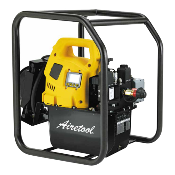
- Page 1 Airetool Instruction Manual ® PL19-6000EN 05/15/2015 ATP III Electric/Hydraulic Pump For additional product information visit our website at http://www.apextoolgroup.com...
-
Page 2: Specifications
PL19-6000EN Airetool ® 05/15/2015 Specifications ATP III Electric/Hydraulic Pump Specifications Pump Model 5526244 (ATP III) Motor 1.7 hp (1,25 kW) Electric Motor Motor Voltage 115 VAC, Single Phase, 50/60 Hz Motor RPM 1,750 Maximum Current Draw 20 Amps 100 psi (7 bar) = 700 in... -
Page 3: System Configuration
PL19-6000EN Airetool ® 05/15/2015 System Configuration Carefully plan your system by selecting components designed to perform the intended operation and which will adequately perform with existing equipment. Always check the product limitations regarding pressure ranges, load capacities and set-up requirements. The system operating pressure must not exceed the pressure rating of the lowest rated component in the system. - Page 4 Intended Use: This pump is designed to work as an integrated tube pulling system in conjunction with the Airetool ATP III gripper type pullers. The Airetool HDQ III gripper type pullers, RAV III and HDP III spear type tube pullers can also be used with this pump.
-
Page 5: Safety First
PL19-6000EN Airetool ® 05/15/2015 Safety First Safety Precautions: cage to safely move the pump. Read instructions, warnings Keep hydraulic equipment away from cautions carefully. Follow safety flames and heat. Excessive heat will precautions to avoid personal injury or soften packing and seals, resulting in fluid property damage during system operation. -
Page 6: Installation
PL19-6000EN Airetool ® 05/15/2015 General Instructions Installation: Connect power to the unit and wait until “OK” is displayed on the LCD before pressing any button on the shroud or Position the pump to ensure that air flow around the pendent (if equipped). - Page 7 PL19-6000EN Airetool ® 05/15/2015 General Instructions User Adjustable Relief Valve: “OK” display by pressing and holding the Menu button for 2 seconds. Limits the pressure by opening the relief valve to redirect the pump’s oil flow to the reservoir at the desired 3.
- Page 8 PL19-6000EN Airetool ® 05/15/2015 General Instructions A. Boot Sequence: The software provides the operator with the following Menus: Firmware 5.5 and earlier: When the pump is connected to electrical power the LCD screen will show: • Automode: Set tube puller Auto Cycle mode ON “FIRMWARE x.x”...
- Page 9 PL19-6000EN Airetool ® 05/15/2015 General Instructions B. Power Failure: D. Motor Overload: Display: “POWER OFF” Display: “MTR OVLD” Figure 8: Power Off Figure 10: Motor Overload The Power Off fault is displayed when the main power The Motor Overload fault is displayed when the electric supply drops to 65% or less of nominal voltage.
-
Page 10: Warning Conditions
PL19-6000EN Airetool ® 05/15/2015 General Instructions F. Oil Level (requires optional float/temperature switch) Warning Conditions: Display: “OIL LEVEL” All warnings notify the operator of an abnormal operating condition, however, allow pump to continue operating. Figure 12: Oil Level Warnings will automatically clear once the issue has been resolved. - Page 11 PL19-6000EN Airetool ® 05/15/2015 General Instructions LCD Menus: C. Set Press or High Press Menu (only available with Automode ON): A. Normal Operation Menu: Figure 16: Set Press or HI PRESS Menu Figure 14: Normal Operation Menu This screen allows the operator to set the Advance port pressure value the tube puller will Auto Cycle at.
- Page 12 PL19-6000EN Airetool ® 05/15/2015 General Instructions E. Motor Menu: of hours the pump has been operated in low-voltage condition. Step forward by pressing the Menu button. Figure 18: Motor Menu G. Advance Menu: This screen allows the operator to read the number of...
- Page 13 PL19-6000EN Airetool ® 05/15/2015 General Instructions I. Local Menu: K. Diagnose Menu: Figure 22: Local Menu Figure 24: Diagnose Menu not used This screen allows the operator to toggle the LOCAL mode ON or OFF, default is OFF. With LOCAL mode...
- Page 14 PL19-6000EN Airetool ® 05/15/2015 General Instructions LCD Hidden Menus: (available when the pressure transducer is installed) A. Calibration Menu: Figure 26: Calibration Menu This screen allows the operator to adjust the pressure value shown on the LCD to match a master gauge. To access this menu: Firmware 5.5 and earlier: Set AUTOMODE to ON and...
- Page 15 PL19-6000EN Airetool ® 05/15/2015 General Instructions Table A - Pump Calibration Step Operator Action LCD Reading Comments Note: There are two methods of producing the needed pressure in steps 11 and 15, using the pumps "motor" or separate "hand pump". Connect a hand...
-
Page 16: Maintenance
Reservoir Full Level Change Oil and Clean Reservoir: The ATP III pump oil is a crisp blue color. Frequently check the oil condition for contamination by comparing the reservoir oil to new unused oil. As a general rule, completely drain an clean the reservoir every 250 hours... - Page 17 PL19-6000EN Airetool ® 05/15/2015 General Instructions Table B - Trouble Shooting Guide Problem Possible Cause Pump will not start No power or wrong voltage Pendant does not function Pump in LOCAL mode Pendant damaged Motor stalls under load Low voltage...
- Page 18 PL19-6000EN Airetool ® 05/15/2015 Electric/Hydraulic Pump Assembly Figure 29 Page 18 Page 18...
- Page 19 PL19-6000EN Airetool ® 05/15/2015 Electric/Hydraulic Pump Assembly Figure 29 Number Description 2902536 EDHP III Electric/Hydraulic Pump Assembly (Factory repair only) ------ Serviceable Electrical Components 2994951 HDP 31 20 Receptacle 8567132 A 100 82 Reverse Switch 2983261 ATS 8835 Cable Clamp...
- Page 20 Tokyo 105-0011, JAPAN Korea Phone: +81-3-6450-1840 Phone: +82-2-2155-0250 Fax: +81-3-6450-1841 Fax: +82-2-2155-0252 Apex Tool Group, LLC Airetool 1000 Lufkin Road ® Apex, NC 27539 Phone: +1 (919) 387-0099 Fax: +1 (919) 387-2614 www.apexpowertools.com PL19-6000EN | 0515 | © 2015 Apex Tool Group, LLC | Printed in USA...
Need help?
Do you have a question about the ATP III and is the answer not in the manual?
Questions and answers