Table of Contents
Advertisement
Quick Links
We advise you to read this manual carefully, as it contains all the instructions for maintaining the
appliance's aesthetic and functional qualities. For further information on the product: www.smeg.com
Contents
56
56
60
60
60
61
61
62
63
63
64
64
65
65
67
67
68
68
71
72
74
75
76
81
81
81
82
83
86
87
89
89
94
99
104
105
106
55
Advertisement
Table of Contents

Related Manuals for Smeg Classica C95GPX9-1


Summary of Contents for Smeg Classica C95GPX9-1
-
Page 1: Table Of Contents
5.5 Access to the terminal board 5.6 Instructions for the installer We advise you to read this manual carefully, as it contains all the instructions for maintaining the appliance’s aesthetic and functional qualities. For further information on the product: www.smeg.com... -
Page 2: Instructions
Instructions 1 Instructions • Keep children under the age of 8 away from the appliance when it 1.1 General safety instructions is in use. • Cleaning and maintenance must Risk of personal injury not be carried out by • During use the appliance and its unsupervised children. - Page 3 Instructions • While cooking do not place • Do not modify this appliance. metal objects, such as cutlery or • Before any operation on the dishes on the hob surface as they appliance (installation, may overheat. maintenance, positioning or • Do not insert pointed metal movement) always wear PPM.
- Page 4 Instructions Risk of damaging the appliance • Do not use plastic cookware or containers for cooking. • Do not use abrasive or corrosive • Do not place sealed tins or detergents (e.g. scouring containers in the oven cavity. powders, stain removers and metallic sponges) on glass parts.
- Page 5 Instructions • Do not put empty pans or frying Installation pans on switched on cooking • This appliance must not be zones. installed in a boat or caravan. • Do not use steam jets to clean the • This appliance must not be appliance.
-
Page 6: Appliance Purpose
Instructions • At the end of the installation, • Do not rest any weight or sit on check for any leaks with a soapy the open door of the appliance. solution, never with a flame. • Take care that no objects are •... -
Page 7: Identification Plate
Instructions 1.5 Identification plate Our appliances are packaged in non- polluting and recyclable materials. The identification plate bears the • Deliver the packing materials to the technical data, serial number and appropriate recycling centre. brand name of the appliance. Do not remove the identification plate for Plastic packaging any reason. -
Page 8: How To Read The User Manual
Instructions 1.7 How to read the user manual This user manual uses the following reading conventions: Instructions General information on this user manual, on safety and final disposal. Description Description of the appliance and its accessories. Information on the use of the appliance and its accessories. -
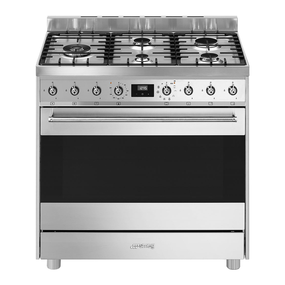
Page 9: Description
Description 2 Description 2.1 General Description 1 Upstand 5 Door 2 Cooking hob 6 Storage compartment 3 Control panel 7 Fan 4 Lamp Rack/tray support frame shelf... -
Page 10: Cooking Hob
Description 2.2 Cooking hob AUX = Auxiliary burner UR2 int. = internal crown ultra rapid burner SR = Semi-rapid burner UR2 ext. = external crown ultra rapid burner R = Rapid burner 2.3 Control panel 1 Hob burner knobs 2 Indicator light Used for lighting and adjusting the hob The indicator light comes on to indicate that burners. -
Page 11: Other Parts
Description 3 Temperature knob Cooling fan This knob allows you to select the cooking The fan cools the oven and comes into temperature. operation during cooking. Turn the knob clockwise to the required The fan causes a steady outflow of air that value, between the minimum and maximum exits from the rear of the appliance and setting. - Page 12 Description WOK ring Deep tray Useful when using a wok. Useful for collecting fat from foods placed on the rack above and for baking cakes, Rack pizza and oven desserts. Rotisserie Used for supporting containers with food during cooking. Oven tray Useful for cooking chicken and all foods that require uniform cooking over their entire surface.
-
Page 13: Use
3 Use Improper use Risk of damage to surfaces 3.1 Instructions High temperature inside the oven • Do not cover the bottom of the oven during use cavity with aluminium or tin foil sheets. Danger of burns • If you wish to use greaseproof paper, place it so that it will not interfere with the •... -
Page 14: First Use
3.3 Using the accessories High temperature inside the storage compartment during use Ring reducers Danger of fire or explosion The ring reducers have to be placed on the hob grids. Make sure they are placed • Do not spray any spray products near properly. - Page 15 Racks and trays Rotisserie Racks and trays have to be inserted into the 1. Insert the 4 supplied bushings in the 4 side guides until they come to a complete corner holes of the deep tray and screw stop. them onto the ring nuts with a suitable tool (such as a screwdriver).
- Page 16 3. Prepare the rotisserie rod with the food 6. Insert the tip of the rod in the rotisserie using the rotisserie rod provided. The clip motor housing on the left of the rear wall forks can be tightened using the of the oven.
-
Page 17: Using The Hob
8. When cooking is complete, remove the The burner may go out when the knob is released: In this case, the thermocouple has tray with the rotisserie. not heated up sufficiently. Wait a few 9. Screw on the handle provided so that moments and repeat the operation. -
Page 18: Using The Oven
Practical tips for using the hob Functions list For better burner efficiency and to minimise Static gas consumption, use pans with lids and of As the heat comes from above and suitable size for the burner, so that the below at the same time, this system flames do not reach up the sides of the pan. - Page 19 Grill Fan with round heating element. The heat coming from the grill The combination of the fan and the element gives perfect grilling results round heating element above all for thin and medium (incorporated in the rear of the thickness meat and, in combination oven) allows you to cook different with the rotisserie (where fitted), foods on several levels, as long as...
-
Page 20: Using The Storage Compartment
3.6 Using the storage compartment There is a storage compartment located at This function is particularly suitable the bottom of the cooker; this can be used for cooking on a single shelf with to store pans or metal objects required to low energy consumption. -
Page 21: Cooking Advice
3.7 Cooking advice • Grilling processes must never last more than 60 minutes. General advice Advice for cooking desserts/pastries and • Use a fan assisted function to achieve biscuits consistent cooking at several levels. • Use dark metal moulds: They help to •... -
Page 22: Programmer Clock
• For successful proving, a container of Setting the time water should be placed in the bottom of the oven. If the time is not set, the oven will not switch on. To save energy • Stop cooking a few minutes before the On the first use, or after a power failure, the time normally used. - Page 23 Timed cooking 7. Press the clock key to reset the programmer clock. Timed cooking is the function which allows a cooking operation It is not possible to set a cooking to be started and then ended after time of more than 10 hours. a specific length of time set by the user.
- Page 24 10. Return the function and temperature 4. Use the key to set the knobs to 0. required minutes. (for example 1 hour) 11. To turn off the buzzer just press any key 5. Press the menu key . The text of the programmer clock.
- Page 25 Modifying the set data Minute minder timer 1. Press the clock key The minute minder timer does not stop the cooking operation but 2. Use the value increase and value rather informs the user when the set time has run out. decrease keys to set the number of minutes required.
- Page 26 Cooking information table Runner Weight Temperature Food Function position from Time (minutes) (kg) (°C) the bottom Lasagne 3 - 4 Static 220 - 230 45 - 50 Pasta bake 3 - 4 Static 220 - 230 45 - 50 Roasted veal Turbo/Fan assisted 180 - 190 90 - 100...
-
Page 27: Cleaning And Maintenance
Cleaning and maintenance 4 Cleaning and maintenance 4.2 Cleaning the appliance We recommend the use of 4.1 Instructions cleaning products distributed by Improper use the manufacturer. Risk of damage to surfaces Recommendations for cleaning the hob • Do not use steam jets to clean the To keep the surfaces in good condition, appliance. -
Page 28: Removing The Door
Cleaning and maintenance Cleaning the igniters and thermocouples For easier cleaning, we recommend removing: • If necessary, clean the igniters and • The door; thermocouples with a damp cloth. • The rack/tray support frames; • If there is any dry residue, remove it with a toothpick or needle. -
Page 29: Cleaning The Door Glazing
Cleaning and maintenance 2. Grasp the door on both sides with both Removing the internal glass panes hands, lift it forming an angle of around For easier cleaning the internal glazing 30° and remove it. panes of the door can be removed. 1. - Page 30 Cleaning and maintenance 3. Remove the middle glazing panes by Removing racks/trays support frames lifting them upwards. Removing the rack/tray support frames enables the sides to be cleaned more easily. To remove the rack/tray support frames: • Pull the frame towards the inside of the oven to unhook it from its groove A, then slide it out of the seats B at the back.
- Page 31 Cleaning and maintenance 1. Move the door lock lever to the right until Manual release of the door lock lever it stops. Improper use Danger of burns • The following operations must always be performed with cold and off appliance. •...
-
Page 32: Pyrolytic Cycle
Cleaning and maintenance 4.5 Pyrolytic cycle Setting up the pyrolytic function 1. Turn the function knob to the Pyrolytic is an automatic high- temperature cleaning procedure symbol. Will appear on the which causes dirt to dissolve. This display alternating with the minimum process makes it possible to clean pyrolytic cycle time (2 hours). -
Page 33: Extraordinary Maintenance
Cleaning and maintenance 7. The door remains locked as long as the During the pyrolytic cycle the fans temperature inside the oven returns to produce a more intense level of safety levels. noise due to a greater rotation speed. This is an absolutely normal 8. - Page 34 Cleaning and maintenance 4. Slide out and remove the light bulb(s). Do not touch the halogen light bulb(s) directly with your fingers, use an insulating material. 5. Fit the new light bulb(s). 6. Refit the cover. Ensure the moulded part of the glass (A) is facing the door.
-
Page 35: Installation
Installation 5 Installation For supplying it with other types of gas, see chapter “5.2 Adaptation to different types 5.1 Gas connection (not valid for the of gas”. The gas inlet connection is threaded ½” external gas (ISO 228-1). Connection with a rubber hose For installation in the UK, please refer to the “Local specifications for Verify that all following conditions are met:... - Page 36 Installation After having tightened the hose Carefully screw the connector 3 to the gas connector(s), push the gas hose 6 onto the connector 1 of the appliance, placing the hose connector and secure it with the clamp seal 2 between them. 5 that is compliant with the standard in force.
- Page 37 Installation Connection with a steel hose with conical Gas connection extension cord fitting 1. Undo the screw A at the back of the Make the connection to the gas mains appliance, under the gas connection. using a continuous wall steel hose whose 2.
- Page 38 Installation 3. Carefully screw the connector 3 to the 4. Carefully screw the assembled gas extension cord 1 of the appliance, extension cord C to the gas connector placing the seal 2 between them. D of the appliance, placing the seal 2 between them.
- Page 39 Installation Room ventilation When the job is complete, the installer must issue a certificate of conformity. The appliance should be installed in rooms that have a permanent air supply in accordance with the standards in force. The room where the appliance is installed must have enough air flow for the regular combustion of gas and the necessary air change in the room itself.
-
Page 40: Adaptation To Different Types Of Gas
Installation 5.2 Adaptation to different types of Adjusting the minimum setting for natural or town gas In case of operation with other types of gas, Light the burner and turn it to the minimum the burner nozzles must be changed and position. - Page 41 Installation Adjusting the minimum setting for LPG Dimensions Position of gas and electrical connections. Tighten the screw located at the side of the cock rod clockwise all the way. Following adjustment to a gas other than the one originally set in the factory, replace the gas setting label on the appliance with the one corresponding to the new gas.
- Page 42 Installation Gas types and Countries Gas types IT GB-IE FR-BE DE RU DK 1 Natural gas G20 20 mbar • • • • • • • • • • G20/25 20/25 mbar • 2 Natural gas G20 • 25 mbar 3 Natural gas G25 25 mbar •...
- Page 43 Installation Burner and nozzle specifications tables 1 Natural gas G20 – 20 mbar UR2 int. UR2 ext. Rated heating capacity (kW) Nozzle diameter (1/100 mm) Pre-chamber (printed on nozzle) (H9) (H1) (H3) Reduced flow rate (W) 1200 2 Natural gas G20 – 25 mbar UR2 int.
- Page 44 Installation 7 Liquid gas – G30/31 – 30/37 mbar UR2 int. UR2 ext. Rated heating capacity (kW) Nozzle diameter (1/100 mm) Pre-chamber (printed on nozzle) Reduced flow rate (W) 1300 Rated flow rate G30 (g/h) Rated flow rate G31 (g/h) 8 LPG G30/31 –...
-
Page 45: Positioning
Installation 5.3 Positioning Any wall units installed above the appliance’s worktop must be positioned at Heavy appliance least Y mm from it. If a hood is installed Crushing hazard above the hob, refer to the hood instruction manual to ensure the correct clearance is left. •... - Page 46 Installation Appliance overall dimensions 900 mm 600 mm B - Class 2 subclass 1 min. 300 mm (Built-in appliance) 900 - 915 mm 750 mm 450 mm 900 mm Minimum distance from side walls or other flammable material. Minimum cabinet width (=A). C - Class 2 subclass 1 (Built-in appliance) The appliance must be installed by...
- Page 47 Installation Positioning and levelling Fastening to the wall Heavy appliance The anti-tip devices must be installed in order to prevent the Risk of damage to the appliance appliance from tipping over. • Insert the front feet first and then the rear 1.
- Page 48 Installation 3. Assemble the fastening bracket. 5. Align the base of the fastening bracket with the ground and tighten the screws to fix the measurements. 6. Use 50 mm for the distance from the side 4. Align the base of the hook on the of the appliance to the bracket holes.
- Page 49 Installation 7. Move the bracket onto the wall and Assembling the upstand mark the position of the holes to be The upstand provided is an drilled in the wall. integral part of the product; it must be fastened to the appliance prior to installation.
-
Page 50: Electrical Connection
Installation 5.4 Electrical connection The appliance can work in the following modes: Power voltage • 220-240 V 2~ Danger of electrocution • Have the electrical connection performed by authorised technicians. • Use personal protective equipment. 3 x 2.5 mm² three-pole cable. •... -
Page 51: Access To The Terminal Board
Installation 3. Install the power supply cable. The aforementioned power cables are sized taking into account the coincidence factor (in compliance with standard EN 60335-2-6). 5.5 Access to the terminal board To connect the power supply cable, access to the terminal board on the rear cover: 1. -
Page 52: Instructions For The Installer
Installation 5.6 Instructions for the installer Fixed connection • The plug must be accessible after Fit the power line with an all-pole installation. Do not bend or trap the disconnection switch in compliance with power cable. installation regulations. The circuit breaker should be located near •...
Need help?
Do you have a question about the Classica C95GPX9-1 and is the answer not in the manual?
Questions and answers