Table of Contents
Advertisement
Quick Links
Advertisement
Table of Contents

Related Manuals for TEDIA PCA-8428


Summary of Contents for TEDIA PCA-8428
- Page 1 Multifunctional DAQ PCIe card PCA-8428/8429/8438/8439 User Guide...
- Page 2 “as is,” without warranty of any kind, either expressed or ® implied, including, but not limited to, its particular purpose. TEDIA reserves the right to make improvements and/or changes to this manual, or to the products and/or the programs described in this manual, at any time.
-
Page 3: Table Of Contents
PCA-8428, PCA-8429, PCA-8438, PCA-8439 User Guide - Table of Contents Table of Contents CE Declaration of Conformity, WEEE 1. Introduction Description ........... - Page 4 PCA-8428, PCA-8429, PCA-8438, PCA-8439 User Guide - CE Declaration of Conformity, WEEE CE Declaration of Conformity ® All TEDIA products described in this user guide comply with the essential requirements of the following applicable European Directives: • Electromagnetic Compatibility (EMC) Directive 2014/30/EU •...
-
Page 5: Introduction
User Guide Introduction Description The PCA-8428/8429/8438/8439 are add-on PCI Express cards intended especially for laboratory and industrial automation and measuring systems. The PCA-8428/8429/8438/8439 cards provide especially these features: • eight or sixteen isolated analog inputs equipped with 14-bit A/D converter •... -
Page 6: Specifications
PCA-8428, PCA-8429, PCA-8438, PCA-8439 User Guide Specifications Analog inputs Number and type of inputs: 8x S.E. (PCA-8428, PCA-8429) 16x S.E. (PCA-8438, PCA-8439) A/D converter resolution: 14 bits Basic input range: ±10 V Programmable gain: 1x, 2x, 4x, 8x, 16x, 32x (ie. -
Page 7: Counters And Encoders
PCA-8428, PCA-8429, PCA-8438, PCA-8439 User Guide Counters, encoders Number of counters: Counting mode: bidirectional with programmable input encoder Counting depth: 32 bits (configurable in range of 2÷4294967295) Counting modes: IRC quadrature modes X1, X2, X4 "up/down", "count/dir", "count/gate" Counting frequency: 2 MHz max. -
Page 8: Interrupt Logic
PCA-8428, PCA-8429, PCA-8438, PCA-8439 User Guide Interrupt logic Interrupt sources: EOS (ie. End Of the measurement Sequence), FIFO memory control circuits, timestamp IRQ generator (1÷255 ms), all digital ports Interrupt trigger event: EOS (software trigger mode), number of samples in FIFO memory (max. 32768 B),... -
Page 9: Installation
Detailed reading of this guide and following the instructions precisely are highly recommended for achieving full quality and to prevent any damage during installation. For further information see manufacturer's website http://www.tedia.eu. Hardware configuration The PCA-84xx card contains a single configuration element - a two-segment DIP switch (the status of this switch can be read by the program to identify multiple cards as CardID value). -
Page 10: Analog Inputs
User Guide Analog Inputs Introduction The PCA-8428 and PCA-8429 cards offer eight analog inputs and the PCA-8428 and PCA-8429 cards offer sixteen analog inputs. Analog inputs are isolated from the computer, the isolation barrier is shared for all analog inputs, resp. it si shared with both analog outputs (ie. all inputs and outputs are solved by one isolated circuit block). - Page 11 Analog Outputs Introduction The PCA-8428 and PCA-8438 cards offer two analog outputs isolated from the computer, the isolation barrier is shared for both analog outputs and all analog inputs (ie. all inputs and outputs are solved by one isolated circuit block).
-
Page 12: Programmable Encoder
PCA-8428, PCA-8429, PCA-8438, PCA-8439 User Guide IRC Encoders and Counters Introduction The PCA-84xx cards contain two independent bidirectional counters equipped with programmable input encoders supporting a wide range of operating modes. In addition, each counter is equipped with minimum/maximum detectors ensuring the capture of extremes between two position readings. -
Page 13: Description Of Digital Ports
Check the Appendix, Figure 9 for detail information. Note: Unfortunately, the concept of bidirectional ports does not provide the overvoltage protection available to other ports of PCI/PCIe TEDIA cards. Interrupt logic The PCT-83xx card allows to trigger an interrupt (simultaneously with the timestamp IRQ generator and FIFO memory control circuits) by any combination of rising or falling edges of the signals of all digital ports. -
Page 14: Alternative Functions Of Dio Ports
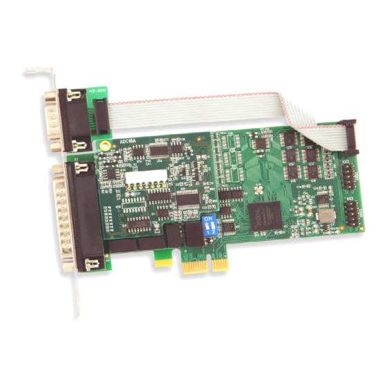
PCA-8428, PCA-8429, PCA-8438, PCA-8439 User Guide Alternative functions of DIO ports Digital ports are used for alternative functions depending on the firmware. The standard PCA-84xx firmware uses the DIO0 port as an input for triggering measurement sequence and as counter inputs:... - Page 15 PCA-8428, PCA-8429, PCA-8438, PCA-8439 User guide - Appendix, Tables and Figures PCA-84xx PCE-8019 ADC16A module (analog IN/OUT) Card ID ID=0 ID=1 ID=2 ID=3 PCA-84xx/LP ADC16A module (analog IN/OUT) Card ID ID=0 ID=1 ID=2 ID=3 Figure 1. Location of switches and connectors on both version of cards.
- Page 16 AIN1 AGND AIN0 AGND Table 1. PCA-8428/8429, D-Sub 25 (male) connector pin assignment. Note: The AOUT0/AOUT1 signals are active only on PCA-8428 card. K1 signal K1 signal - - - - - - - - - - - - AOUT1 (see note below)
- Page 17 PCA-8428, PCA-8429, PCA-8438, PCA-8439 User guide - Appendix, Tables and Figures KX1/KX2/KX3 signal KX1/KX2/KX3 signal DIO00/08/16 DIO01/09/17 DIO02/10/18 DIO03/11/19 DIO04/12/20 DIO05/13/21 DIO06/14/22 DIO07/15/23 5V (viz. technické parametry) Table 3. Header type connector pin assignment. Note: In case of the standard format card, the DIO0 port is accessible on the card bracket via adapter cable PCE-8019 terminated with D-Sub 9 connector.
- Page 18 PCA-8428, PCA-8429, PCA-8438, PCA-8439 User guide - Appendix, Tables and Figures Figure 2. Pin layout on D-Sub 25 (male), D-Sub 9 (male) and header type connectors (2x 5 pins, 2.54 mm pitch). PCIe card AIN0 PROG FIFO AIN7 (AIN15) AGND SCAN LOGIC Figure 3.
- Page 19 PCA-8428, PCA-8429, PCA-8438, PCA-8439 User guide - Appendix, Tables and Figures PCIe card AOUT0 1 Ohm approx. AOUTx >2kOhm AOUT1 1 Ohm approx. AGND AGND power supply ±15V / 15mA Figure 4. Simplified schematic of analog outputs. The schematic shows two D/A converters (DAC) and two output amplifiers (OPA).
- Page 20 PCA-8428, PCA-8429, PCA-8438, PCA-8439 User guide - Appendix, Tables and Figures IRCCNTx_A = "up" IRCCNTx_B = "down" counter value Figure 6. "Up/Down" counting mode. at least 25 ns long when filter is disabled, resp. 310 ns when enabled) (the encoder detects both "up/down" signals at level L and signals as an error) IRCCNTx_A = "count"...
- Page 21 PCA-8428, PCA-8429, PCA-8438, PCA-8439 User guide - Appendix, Tables and Figures INPUT mode of DIO port PCIe card DIOxx DIOxx data data OUTPUT mode of DIO port DOUT DIOxx => INPUT >500R => OUTPUT DIO port mode Figure 9. Simplified schematic of DIO ports.
- Page 22 PCA-8428, PCA-8429, PCA-8438, PCA-8439 User Guide - Notes ........................................................................................................................................................................................................................................................................................................................................................................................................................................................................................................................................................................................................................................................................................................................................................................................................
Need help?
Do you have a question about the PCA-8428 and is the answer not in the manual?
Questions and answers