Table of Contents
Advertisement
Quick Links
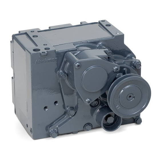
BLACKMER GLOBAL DISPENSER PUMP
OPERATION AND MAINTENANCE INSTRUCTIONS
TABLE OF CONTENTS
..................................................................1-
.........................................................................
Pressure Control Valve (PCV) Adjustment............2
..................................................................
Draining Pump.......................................................2
Strainer/Check Valve Removal..............................2
Strainer/Check Valve Installation...........................3
Pressure Control Valve (PCV) Removal................3
Pressure Control Valve (PCV) Installation.............3
Pump Cartridge Removal ......................................3
Pump Cartridge Installation ...................................4
Sump Float Removal.............................................4
Sump Float Installation..........................................4
OIML Switch Removal...........................................5
OIML Switch Installation........................................5
PUMP PARTS LISTS..............................................7-10
Models 102 & 201..................................................7
......................................................................
Models:
...........................................................................
NOTE: Numbers in parentheses following individual parts
indicate reference numbers on the corresponding Blackmer
Parts List.
WITH PARTS LIST
MODEL: GDP
Page
2
2
2
...5
...................6
UHF Pumps
8
9
..
10
..........................
11
..........................................
SAFETY DATA
This is a SAFETY ALERT SYMBOL.
When you see this symbol on the product, or in the manual, look for
one of the following signal words and be alert to the potential for
personal injury, death or major proper ty damage.
Warns of hazards that WILL cause serious personal injury,
death or major proper ty damage.
Warns of hazards that CAN cause serious personal injury,
death or major property damage.
Warns of hazards that CAN cause personal injury
or property damage.
NOTICE:
Indicates special instructions which are very
impor tant and must be followed.
NOTICE:
Blackmer GDP pumps MUST only be installed in
systems which have been designed by qualified
engineering personnel. The system MUST conform to
all applicable local and national regulations and safety
standards.
This manual is intended to assist in the operation and
maintenance of the Blackmer GDP pump, and MUST
be kept with the pump.
Blackmer GDP pump service shall be performed by
qualified technicians ONLY. Service shall conform to
all applicable local and national regulations and safety
standards.
Thoroughly review the pump instructions and hazard
warnings, BEFORE performing any work on the
Blackmer GDP pump.
Maintain ALL system and Blackmer GDP pump
operation and hazard warning decals.
964800
INSTRUCTIONS AND
PARTS LIST NO. 1701-A00
Page 1 of 12
Section
1701
Effective
February 2004
Replaces October 2003
Advertisement
Table of Contents

Related Manuals for BLACKMER GDP 102


Summary of Contents for BLACKMER GDP 102
-
Page 1: Table Of Contents
Pressure Control Valve (PCV) Removal....3 Pressure Control Valve (PCV) Installation.....3 NOTICE: Pump Cartridge Removal ........3 Blackmer GDP pumps MUST only be installed in Pump Cartridge Installation ........4 systems which have been designed by qualified Sump Float Removal..........4 engineering personnel. The system MUST conform to Sump Float Installation..........4... -
Page 2: Safety Data
SAFETY DATA USE CARE WHEN WORKING IN A FAILURE TO DISCONNECT AND POTENTIALLY DANGEROUS LOCKOUT ELECTRICAL POWER ENVIRONMENT OF FLAMMABLE BEFORE ATTEMPTING MAINTENANCE CAN CAUSE SHOCK, BURNS OR FUELS, VAPORS AND HIGH VOLTAGE. Hazardous fluids can DEATH. FIRE OR EXPLOSION COULD RESULT cause fire, serious Hazardous voltage. -
Page 3: Strainer/Check Valve Installation
MAINTENANCE PRESSURE CONTROL VALVE INSTALLATION 1. Inspect valve for damage or excessive wear. Replace if necessary. 2. Install pressure control valve in reverse order of removal. Refer to Figure 2. Apply a light application of grease on the cover O-ring (14) to help keep the O-ring from being damaged during installation. -
Page 4: Pump Cartridge Installation
MAINTENANCE SUMP FLOAT REMOVAL Pump will have poor suction or sump overflow if sump float mechanism is worn or damaged Head Gasket (8) Tools Required: 13 mm Socket Wrench (or 1/2” Socket Wrench) 4 mm Allen Wrench 1. Drain the pump following the procedure outlined under the “Draining Pump”... -
Page 5: Oiml Switch Removal
MAINTENANCE OIML SWITCH INSTALLATION 4. Install the sump cover gasket (3). Correctly position the gasket onto all sealing surfaces. 1. Apply very thin film of thread sealing compound onto 5. Lower the sump cover (4) gently into place over the gasket thread beginning about 3mm from the end. -
Page 6: Repair Kits Parts List
REPAIR KITS PARTS LIST FOR UHF PUMPS KIT NO. DESCRIPTION PARTS INCLUDED IN KIT Ref. No. Part Description Part No. 894865 Inlet Strainer Kit, UHF Strainer, UHF 724895 O-Ring, Strainer Cover 702332 894861 Check Valve Kit Check Valve Assembly 894840 O-Ring, Strainer Cover 702332 Strainer, Dome... -
Page 7: Pump Parts Lists
PUMP PARTS LIST- MODELS 102 & 201 REF. NO. DESCRIPTION OF PARTS QTY. PART NO. Casing, Pump Float Assembly, Sump (Std) 894876 Gasket, Sump 384861 Sump Cover Assembly Screw, Taptite 924002 Wave Spring* 903408 Pump Cartridge* 894805 Gasket, Head* 384860 Head Pressure Control Valve (PCV)* 454800... -
Page 8: Model 206
PUMP PARTS LIST - MODEL 206 REF. NO. DESCRIPTION OF PARTS QTY. PART NO. Casing, Pump Float Assembly, Sump (Std) 894876 Gasket, Sump* 384861 Sump Cover Assembly Screw, Taptite 924002 Wave Spring* 903408 Pump Cartridge* 894805 Gasket, Head* 384860 Head Pressure Control Valve (PCV)* 454800 Plug... -
Page 9: M00955B107, 203, 204, 207, 208, 705, & 707
PUMP PARTS LIST - STANDARD FLOW PUMPS MODELS M00955B107, 203, 204, 207, 208, 705, 707 REF. NO. DESCRIPTION OF PARTS QTY. PART NO. Casing, Pump Float Assembly, Sump 894876 Gasket, Sump* 384862 Sump Cover Assembly Screw, Taptite 924002 Wave Spring* 903408 Pump Cartridge* 894805... - Page 10 PUMP PARTS LIST - UHF PUMPS: MODELS 602 AND 605 REF. NO. DESCRIPTION OF PARTS QTY. PART NO. Casing, Pump Float Assembly, Sump 894876 Gasket, Sump* 384861 Sump Cover Assembly Screw, Taptite 924002 Wave Spring* 903408 Pump Cartridge* 894806 Gasket, Head* 384860 Head Pressure Control Valve (PCV)*...
-
Page 11: Pump Troubleshooting
PUMP TROUBLESHOOTING NOTICE: MAINTENANCE SHALL BE PERFORMED BY QUALIFIED TECHNICIANS ONLY, FOLLOWING THE APPROPRIATE PROCEDURES AND WARNINGS AS PRESENTED IN THIS MANUAL. SYMPTOM PROBABLE CAUSE Pump not priming or 1. Suction line obstruction. excessive time to prime 2. Air leak in suction line. 3. - Page 12 Accessories Dispensing, Transfer, In-line Gear Reducers, Bypass Valves, Strainers Visit www.blackmer.com for complete information on all Blackmer products 1809 Century Avenue, Grand Rapids, Michigan 49503-1530 U.S.A. Telephone: (616) 241-1611 • Fax: (616) 241-3752 E-mail: blackmer@blackmer.com • Internet Address: www .blackmer.com...
Need help?
Do you have a question about the GDP 102 and is the answer not in the manual?
Questions and answers