
Subscribe to Our Youtube Channel
Related Manuals for Johnson Controls tyco PG8WLSHW8


Summary of Contents for Johnson Controls tyco PG8WLSHW8
- Page 1 PG8WLSHW8 and PG9WLSHW8 IQ Hardwire PowerG Wired to Wireless Converter Installation Manual *29010878R005* 29010878R005...
- Page 2 PG8WLSHW8 and PG9WLSHW8 IQ Hardwire PowerG Wired to Wireless Converter Installation Manual...
-
Page 3: Table Of Contents
Contents Safety instructions............................5 Introduction..............................6 Technical Specifications........................... 7 Installing the equipment..........................9 Mounting the module......................... 10 Mounting the enclosure..........................10 Mounting the power adapter........................10 Wiring the zones..........................12 Normally open and normally closed wiring....................13 Single end-of-line resistors........................13 Double end-of-line resistors........................15 Wiring programmable outputs...................... - Page 4 Simplified EU declaration of conformity................... 35 EULA.................................36 SOFTWARE PRODUCT LICENSE......................36 Limited warranty............................39 International Warranty........................39 Warranty Procedure..........................39 Conditions to Void Warranty......................39 Items Not Covered by Warranty......................39 Disclaimer of Warranties........................40 Out of Warranty Repairs........................40 Trademark...............................41 PG8WLSHW8 and PG9WLSHW8 IQ Hardwire PowerG Wired to Wireless Converter Installation Manual...
-
Page 5: Safety Instructions
Safety instructions Read the safety information before you install the equipment. Important: This equipment must be installed by a skilled person only. A skilled person is an installer with appropriate technical training. The installer must be aware of potential hazards during installation and measures available to minimize risks to the installer and other people. -
Page 6: Introduction
Introduction The IQ Hardwire PowerG Wired to Wireless Converter converts existing hardwired zones to PowerG wireless zones. There are two models, the PG8WLSHW8 and PG9WLSHW8, and each provide eight hardwired zones and four programmable outputs. This document describes how to mount the enclosure, wire zones, connect the battery, enroll devices, and troubleshoot. -
Page 7: Technical Specifications
Technical Specifications The following table outlines the electrical ratings of the components of the IQ Hardwire PowerG Wired to Wireless Converter. Table 2: Technical specifications Type Description DC input voltage and current Use the provided external power adapter with the following ratings. - Page 8 Table 2: Technical specifications Type Description Bell circuit voltage and current 11.3 VDC to 12.5 VDC, maximum current 700 mA continuous. For EN50131 Grade 2 applications, the voltage rating is 9.6 VDC to 13.75 VDC. Note: The bell output supports continuous burglary alarms, T3 fire alarms, and T4 CO alarms.
-
Page 9: Installing The Equipment
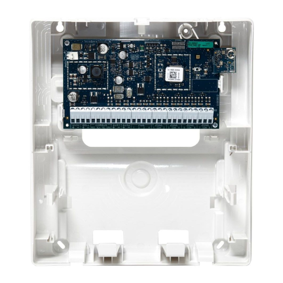
Installing the equipment This section describes how to mount the enclosure, install the battery, and wire the system. The enclosure has three breakaway tabs that you can use for wiring access during installation. There are also two slots for the battery strap to pass through. For more information, see the highlighted areas in Figure 1. -
Page 10: Mounting The Module
Callout Description Breakaway tabs Slots for the battery strap Note: Securing the battery in the enclosure with the battery strap is optional. The battery strap is sold separately. Wall tamper screw Mounting the module This section describes how to mount the enclosure and the external power adapter. Mounting the enclosure To mount the PG8WLSHW8 and PG9WLSHW8 enclosure, complete the following steps: Use the four ST 6X1/2 type 25 Phil screws provided to secure the enclosure to the wall. - Page 11 Figure 2: Mounting locations Callout Description PC Link connection. Note: Pin one is on the right. When you connect to the PC Link, make sure that the PCB side of the PC Link connector aligns with the white line on the module PCB, and use only the four pins on the right. Wall tamper screw Enrollment button PG8WLSHW8 and PG9WLSHW8 IQ Hardwire PowerG Wired to Wireless Converter Installation Manual...
-
Page 12: Wiring The Zones
Callout Description Status LED Power adapter mounting tabs. Alternate adapter is plug-in style (HS40WPSA). Use the following table to determine the distance and gauge for the secondary wiring. Table 3: Wiring distance and gauge Distance (m/ ft) Gauge (AWG) 2/ 6.5 3/ 10 4/ 13 For UL and ULC installations, use a primary input with ratings of 120 VAC, 60 Hz, and 1.2 A. -
Page 13: Normally Open And Normally Closed Wiring
Note: Distances are based on a maximum wiring resistance of 100 Ω. Normally open and normally closed wiring Wire normally closed devices in series and normally open devices in parallel. To wire hardwired devices, complete the following steps: Wire the device to any Zone terminal. Wire the device to any COM terminal. - Page 14 The following figure shows the different wiring configurations for SEOL resistors. The image on the left shows one normally closed contact with an SEOL resistor, and the image on the right shows one normally open contact with an SEOL resistor. Note: SEOL resistors can have a resistance between 1 kΩ...
-
Page 15: Double End-Of-Line Resistors
Table 6: SEOL zone status Resistance Description Status 0 Ω Shorted wire, loop shorted Alarm 1 kΩ to 10 kΩ Contact closed Secure Infinite Broken wire, loop open Alarm for burglary zones and Trouble for fire zones Double end-of-line resistors If you use DEOL resistors at the end of a zone loop, the second resistor detects if a zone is in alarm, tampered, or faulted. -
Page 16: Wiring Programmable Outputs
Table 7: DEOL zone status Resistance Description Status 0 Ω Shorted wire, loop shorted Trouble 5600 Ω Contact closed Secure Infinite Broken wire, loop open Tamper 11200 Ω Contact open Alarm Wiring programmable outputs You can use the programmable (PGM) outputs to activate devices such as LEDs and buzzers. To wire an output to the PGM, complete the following steps: Connect the positive wire from the device to the AUX+ terminal. -
Page 17: Wiring A Fire Zone To The Pgm2 Configured As A 2-Wire Loop
Callout Description LED indicator 680 Ω resistor (typical value) To wire the relay output, see Figure 7. Figure 7: Relay output wiring Callout Description AUX terminals PGM terminals Relay (RM-1 and RM-2) To normally open connection To normally closed connection To COM terminal Wiring a fire zone to the PGM2 configured as a 2-wire loop When you wire a 2-wire smoke detector, observe the following guidelines:... - Page 18 • For UL and ULC residential fire applications, use only the AUX2 output to provide power to smoke and CO detectors. If you program PGM2 for use with a 2-wire smoke detector, you must wire it according to the following figure: Figure 8: 2-wire smoke detector wiring AUX2 Callout...
-
Page 19: Wiring A 4-Wire Smoke, Heat, Or Co Detector
Table 9: 2-wire smoke detector initiation circuit Item Specification DC output voltage 10.0 VDC to 13.8 VDC Detector load 2 mA maximum SEOL 2200 Ω Maximum capacitance 10 μF Maximum number of detectors per loop 18 without sounders Maximum ripple 45 mV Resting voltage and time 0.2 VDC/ 5 seconds... -
Page 20: Wiring Auxiliary Power
Callout Description 4-wire smoke, heat, or CO detector power terminals 4-wire smoke, heat, or CO detector alarm terminals 4-wire smoke, heat, or CO trouble terminals, if provided 5600 Ω single end-of-line resistor 100 Ω alarm initiating loop RM-1 or RM-2 power loop supervisory relay, 12 VDC, 35 mA. Module zone input Note: You can manually configure PGM2 as a 2-wire smoke loop in panel programming. -
Page 21: Wiring The Module
Figure 11: Installing the battery Wiring the module This section describes how to wire the external power supply and battery. For more information, see Figure 12. Wiring the power supply To wire the external power supply, complete the follow steps: On the power supply, secure the wires to the terminals. -
Page 22: Wiring A Keypad/Hsm2108/Hsm2300
Figure 12: Wiring the battery Important: You must maintain a minimum separation of 6.4 mm (0.25 in.) at all points between non-power limited battery wiring and all other power limited wiring connections. Do not route any wiring over circuit boards. You must maintain a minimum separation of 25.4 mm (1 in.) between all wiring and the PCB. - Page 23 Note: Starting with v1.20 Proximity tags are supported on the PG8WLSHW8 or PG9WLSHW8. You can use the keypad to perform the following operations: To arm and disarm the system. To view zone status. To view partition status. To use the keypad function keys. The * menus support *1 Bypass, *2 Troubles, *3 Alarm Memory, *4 Chime, *6 User Functions (keypad buzzer, contrast and brightness only), *7 Command Outputs 1-4, *9 No Entry Arm, and *0 Quick Arm/Quick Exit.
-
Page 24: Silencing Fire Alarm Or Co Alarm Bells
When you install multiple keypads and modules, wire keypads using the same partition on the same module to improve keypad performance. Keypads on partition one should be wired into module one, and keypads on partition two should be wired into module two. Silencing fire alarm or CO alarm bells This section describes how to silence Fire alarms or CO Alarms Fire alarms or CO Alarms can be silenced by entering a valid access code. -
Page 25: Enrolling The Module
Enrolling the module Before you enroll the module, ensure that all hardwired zones, PGM, AUX, and BELL are wired to the module. To enroll the module, complete the following steps: Enable enrollment through panel programming. For more information, refer to the Qolsys IQPanel2 or Qolsys IQPanel4 Installation Manual. -
Page 26: Enrolling Wired Zones Automatically
Enrolling wired zones automatically When you successfully enroll the module to the control panel, eight hardwired zones are added to the control panel. The zones display on the control panel with the same ID as the module and zone label as the corresponding hardwired input. Enable and configure each zone input and PGM using the zone configuration options on the control panel. -
Page 27: Enrolling A Keypad/Zone Expander/Power Supply
Enrolling a keypad/zone expander/power supply To enroll a keypad or device on to the module, complete the following steps: Select Settings > Advanced Settings > Installation > Devices > Security Sensors. To automatically enroll all keypads and modules that are correctly wired to the module, select Auto Learn. -
Page 28: Attaching The Cover
Attaching the cover To attach the front cover to the enclosure, follow the numbered steps in Figure 14. Example: Figure 14: Attaching the cover PG8WLSHW8 and PG9WLSHW8 IQ Hardwire PowerG Wired to Wireless Converter Installation Manual... -
Page 29: Status Leds
Status LEDs There is one multicolored LED on the module. The following table describes the status of the module based on the color of the LED. Table 12: Status LEDs Mode Description Turn on The red LED is on while the module turns on. Placement test The color of the LED shows the signal strength of the enrolled device. -
Page 30: Troubleshooting
Troubleshooting To perform a local update of the firmware, use DLS 5 or higher. The status LED indicates if a trouble condition is present. You can view the trouble conditions in detail on the alarm panel. The following table describes the trouble states that the module can detect. Table 13: Troubleshooting Trouble Description... -
Page 31: Wiring Diagram
Wiring diagram For an overview of how to wire the system, see the following figure. Figure 15: Wiring diagram Applicable standards Warning: High voltage. Disconnect DC power before servicing. UL985 Household Fire Warning S ystem Units Incorrect connections may result in PTC failure or improper UL1023 Househole Burglar Alarm S ystem Units UL1610 S tandard for Central-S tation Burglar-Alarm Units operation. -
Page 32: Fcc And Ised Canada Information
FCC and ISED Canada Information This information applies to model PG9WLSHW8. Modification statement Tyco Safety Products Canada Ltd. has not approved any changes or modifications to this device by the user. Any changes or modifications could void the user’s authority to operate the equipment. Tyco Safety Products Canada Ltd. -
Page 33: Fcc Class B Digital Device Notice
FCC class B digital device notice This equipment has been tested and found to comply with the limits for a Class B digital device, pursuant to part 15 of the FCC Rules. These limits are designed to provide reasonable protection against harmful interference in a residential installation. -
Page 34: Ul And Ulc Notes
UL and ULC notes The model PG9WLSHW8 has been listed by UL and ULC for commercial burglary and residential fire/burglary applications in accordance with the requirements in the Standards UL1610/UL1023/ UL985 and ULC-S304/ULC-S545. For UL/ULC installations, use this device only in conjunction with compatible wireless receivers/control panels combination, model Qolsys IQPanel2 and IQPanel4. -
Page 35: European Ce Compliance And Certalarm Certification
European CE Compliance and CERTALARM Certification This information applies to model PG8WLSHW8. According to EN50131-1,this equipment can be applied in installed systems up to and including Security Grade 2, Environmental Class II. UK: The PG8WLSHW8 is suitable for use in systems installed to conform to PD6662:2017 at Grade 2 and environmental class II. -
Page 36: Eula
EULA IMPORTANT - READ CAREFULLY DSC Software purchased with or without Products and Components is copyrighted and is purchased under the following license terms: • This End- User License Agreement (“EULA”) is a legal agreement between You (the company, individual or entity who acquired the Software and any related Hardware) and Digital Security Controls, a division of Tyco Safety Products Canada Ltd. - Page 37 • Separation of Components - The SOFTWARE PRODUCT is licensed as a single product. Its component parts may not be separated for use on more than one HARDWARE unit. • Single INTEGRATED PRODUCT - If You acquired this SOFTWARE with HARDWARE, then the SOFTWARE PRODUCT is licensed with the HARDWARE as a single integrated product.
- Page 38 • LIMITATION OF LIABILITY; WARRANTY REFLECTS ALLOCATION OF RISK - IN ANY EVENT, IF ANY STATUTE IMPLIES WARRANTIES OR CONDITIONS NOT STATED IN THIS LICENSE AGREEMENT, DSC’S ENTIRE LIABILITY UNDER ANY PROVISION OF THIS LICENSE AGREEMENT SHALL BE LIMITED TO THE GREATER OF THE AMOUNT ACTUALLY PAID BY YOU TO LICENSE THE SOFTWARE PRODUCT AND FIVE CANADIAN DOLLARS (CAD$5.00).
-
Page 39: Limited Warranty
Limited warranty Digital Security Controls warrants the original purchaser that for a period of twelve months from the date of purchase, the product shall be free of defects in materials and workmanship under normal use. During the warranty period, Digital Security Controls shall, at its option, repair or replace any defective product upon return of the product to its factory, at no charge for labour and materials. -
Page 40: Disclaimer Of Warranties
product label and lot number or serial number; (iii) products disassembled or repaired in such a manner as to adversely affect performance or prevent adequate inspection or testing to verify any warranty claim. Access cards or tags returned for replacement under warranty will be credited or replaced at DSC's option. -
Page 41: Trademark
Product offerings and specifications are subject to change without notice. Actual products may vary from photos. Not all products include all features. Availability varies by region; contact your sales representative. © 2022 Johnson Controls. All rights reserved. JOHNSON CONTROLS, TYCO and DSC are trademarks of Johnson Controls. Toronto, Canada ∙ www.dsc.com Tech support: 1-900-3630 (Canada and U.S), or 1-905-760-3000 (International)
Need help?
Do you have a question about the tyco PG8WLSHW8 and is the answer not in the manual?
Questions and answers