Table of Contents
Advertisement
Quick Links
Instruction Manual
P6021
60 MHz Current Probe
070-0947-05
Warning
The servicing instructions are for use by qualified
personnel only. To avoid personal injury, do not
perform any servicing unless you are qualified to
do so. Refer to all safety summaries prior to
performing service.
www.tektronix.com
Advertisement
Table of Contents

Related Manuals for Tektronix P6021


Summary of Contents for Tektronix P6021
- Page 1 Instruction Manual P6021 60 MHz Current Probe 070-0947-05 Warning The servicing instructions are for use by qualified personnel only. To avoid personal injury, do not perform any servicing unless you are qualified to do so. Refer to all safety summaries prior to performing service.
- Page 3 Copyright Tektronix, Inc. All rights reserved. Tektronix products are covered by U.S. and foreign patents, issued and pending. Information in this publication supercedes that in all previously published material. Specifications and price change privileges reserved. Tektronix, Inc., P.O. Box 500, Beaverton, OR 97077 TEKTRONIX and TEK are registered trademarks of Tektronix, Inc.
- Page 4 WARRANTY Tektronix warrants that this product will be free from defects in materials and workmanship for a period of one (1) year from the date of shipment. If any such product proves defective during this warranty period, Tektronix, at its option, either will repair the defective product without charge for parts and labor, or will provide a replacement in exchange for the defective product.
-
Page 5: Table Of Contents
........... . . P6021 Instruction Manual... - Page 6 Table of Contents List of Figures Figure 1: The P6021 Probe and Termination ....Figure 2: Insertion Impedance of the P6021 .
-
Page 7: General Safety Summary
Do Not Operate With Suspected Failures. If you suspect there is damage to this product, have it inspected by qualified service personnel. Do Not Operate in Wet/Damp Conditions. Do Not Operate in an Explosive Atmosphere. Keep Product Surfaces Clean and Dry. P6021 Instruction Manual... - Page 8 WARNING indicates an injury hazard not immediately accessible as you read the marking. CAUTION indicates a hazard to property including the product. Symbols on the Product. The following symbols may appear on the product: CAUTION Double Protective Ground Insulated Refer to Manual (Earth) Terminal P6021 Instruction Manual...
-
Page 9: Service Safety Summary
Safety Summary and the General Safety Summary before performing any service procedures. Do Not Service Alone. Do not perform internal service or adjustments of this product unless another person capable of rendering first aid and resuscitation is present. To avoid electric shock, do not touch exposed connections. P6021 Instruction Manual... -
Page 10: Contacting Tektronix
This phone number is toll free in North America. After office hours, please leave a voice mail message. Outside North America, contact a Tektronix sales office or distributor; see the Tektronix web site for a list of offices. P6021 Instruction Manual... -
Page 11: Operator Information
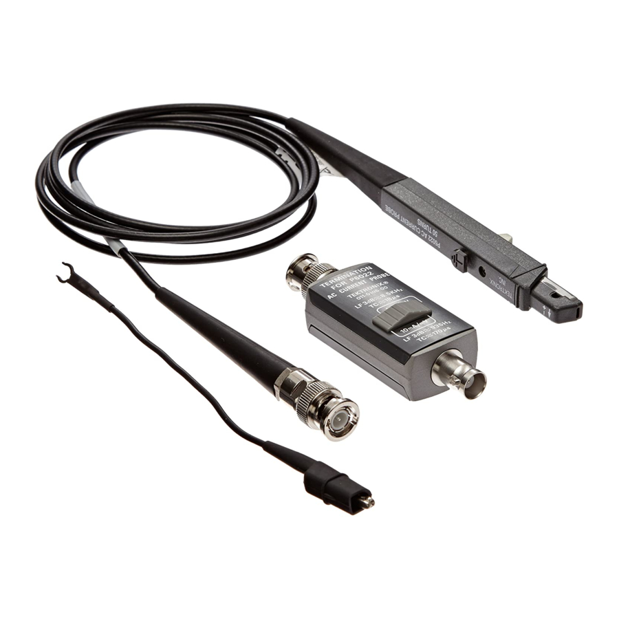
In the standard configuration, the P6021 probe comes with a 5-foot cable and termination. The following option is also available. Option 03. 9-foot cable with termination... -
Page 12: Figure 1: The P6021 Probe And Termination
To avoid damaging the probe, do not disconnect the probe termination and leave the P6021 clamped around the conductor when measuring high currents. Leaving the probe cable unterminated can cause a high voltage to develop in the secondary winding, which may damage the current probe transformer. - Page 13 Your P6021 may be used with the following optional accessory: CT-4 Current Probe — The CT-4 is a robust clip-on transformer that extends the current range of the P6021 up to 1000 amps (provided the amp-second rating is not exceeded). The CT-4 has receptacles for current probes in either 20:1 or 1000:1 step-down ratios.
-
Page 14: Operating Considerations
Operator Information Operating Considerations The information in this section will help you make effective use of your P6021 probe. Features and Controls Sensitivity Control — The P6021 termination has a control that allows you to select probe sensitivity. The switch has two positions: 2 mA/mV and 10 mA/mV. -
Page 15: Figure 2: Insertion Impedance Of The P6021
When you insert a conductor into the probe, you add impedance to the circuit you are measuring. This additional impedance affects signals; this is particularly important if you are measuring fast rise times. Figure 2 illustrates the equivalent circuit with the additional impedance introduced by the P6021. 1.7 nH .004... - Page 16 Operator Information Probe Shielding The P6021 is shielded to minimize the effect of external magnetic fields. However, strong fields can interfere with the current signal being measured. If you suspect that an external field is interfering with your measurement, remove the probe from the conductor, but keep it in the same location as when you made the suspect measurement.
-
Page 17: Service Information
Service Information Warranted Characteristics This section lists the various warranted characteristics that describe the P6021 Current Probe. Included are warranted electrical and environmental characteris- tics. Warranted characteristics are described in terms of quantifiable performance limits which are warranted. The electrical characteristics listed in Table 1 apply under the following... -
Page 18: Table 2: Warranted Environmental Characteristics
(A · s) product greater than 500(A · s) reduces probe output to zero due to core saturation Maximum Working 300 VAC or VDC, CAT I, and 600 V limited to Input Voltage <10 ms and <25% duty factor. (uninsulated conductors) P6021 Instruction Manual... -
Page 19: Figure 3: Probe And Termination Input Current Vs
Safety requirements for electrical equipment for measurement, control, and laboratory test EN 61010-2-032:1995 Part 2-032: Particular requirements for hand-held current clamps for electrical measurements and test Listed UL1244, Third Edition Electrical and electronic measuring and test equipment P6021 Instruction Manual... -
Page 20: Typical Characteristics
Do not operate in environments where conductive pollutants may be present. Typical Characteristics This section lists the various typical characteristics that describe the P6021 Current Probe. Included are typical electrical and mechanical characteristics. Typical characteristics are described in terms of typical or average performance. -
Page 21: Figure 4: Typical P6021 Phase Response
Maximum Conductor Diameter 0.141 in 3.58 mm Frequency 100 Hz 1 kHz 10 kHz 100 kHz 1 MHz 10 MHz 100 MHz Termination at 10 mA -100 Termination at 2 mA -150 -200 Figure 4: Typical P6021 phase response P6021 Instruction Manual... -
Page 22: Circuit Description
As indicated on the probe body, the turns ratio of the P6021 is 125:1. This refers to the number of windings in the secondary of the probe transformer. -
Page 23: Figure 5: P6021 Schematic Diagram
FERRITE SW20 TRANSFORMER 1.6 H CORE (3T) (6T) 5-25 5-25 50 H COMP 10mA/mV 61.9 ADDED AFTER 1249 50 H 64 H 2.5-9 24.9 24.3 51.1 SHIELD P6021 PROBE P6021 PASSIVE TERMINATION Figure 5: P6021 schematic diagram P6021 Instruction Manual... -
Page 24: Performance Verification
This section provides procedures to check the performance of the P6021 or to calibrate it. These procedures require the equipment listed in Table 7. Specifica- tions given are the minimum necessary for accuracy. -
Page 25: Table 7: Equipment List
0.60% Sinewave voltage into 50 (100 mA), Wavetek 9100 with option 100:250, 50 kHz to >60 MHz, Tektronix SG 5030, SG 503 1.5% flatness Digital Multimeter (DMM) 5 1/2 digits or better Keithley 2000, HP 3458A RMS ACV 50 mV to 1.0 V, 10 kHz, 0.35%... -
Page 26: Adjustment Procedures
1. Insert a small screwdriver between the cover and the termination near the part number, and gently pry up the top cover of the P6021 termination by twisting the screwdriver. Leave the bottom cover on, since it must be in place when the termination is in use. - Page 27 Or, if you are using a PG506A, set the function to Fast Rise. 3. Connect the P6021 probe BNC connector to the termination. 4. Connect the P6021 termination to the oscilloscope Ch 1 input. 5. Set the P6021 termination sensitivity to 2 mA/mV.
-
Page 28: Figure 6: Connecting The Probe To The Calibration Fixture
20%. Adjust the position and trigger controls for a vertically centered pulse display with approximately 2 divisions of baseline and 8 divisions of topline displayed. This will allow for an accurate pulse amplitude reference measurement at 50 ns/div. P6021 Instruction Manual... -
Page 29: Figure 7: Location Of Probe Adjustments
Adjust R36 for flat response. (Controls front corner, first 5 ns.) d. Adjust C25 to minimize wrinkles in the 10 to 20 ns domain. e. Adjust C22 to minimize wrinkles in the 15 to 25 ns domain. P6021 AC CURRENT PROBE 125 TURNS TEKTRONIX, INC... -
Page 30: Figure 8: Location Of Termination Adjustments
Digital oscilloscopes with zoom mode can increase resolution. Noise and statistical variations will limit the useful resolution. Turn gating off after completing measurements. All of the adjustments interact; you may have to repeat adjustments to meet all specifications. P6021 Instruction Manual... - Page 31 6. Set the calibrator output to 318.198 mA (0.90 A 7. Change the calibrator frequency to 30 kHz. 8. Allow the DMM reading to stabilize. The DMM must read between 0.1543 and 0.1639 V (0.1591 V nominal). 9. Set the calibrator output to off. P6021 Instruction Manual...
- Page 32 4. Set the oscilloscope vertical sensitivity to 100 mV/div and the horizontal scale to 20 s/div. 5. Set the calibrator for a 10 kHz, 0.35355 A (1 A ) output with the delta % function is turned off. P6021 Instruction Manual...
- Page 33 2. Set the oscilloscope vertical sensitivity to 50 mV/div and the horizontal scale to 20 s/div. 3. Set the calibrator for a 10 kHz, 1.06066 A (3 A ) output with the delta % function is turned off. P6021 Instruction Manual...
- Page 34 15. If using cursors to take this measurement, adjust the cursors to measure the peak-to-peak amplitude. Use averaging if possible. 16. Set the calibrator % delta to off. 17. Set the calibrator output to off. P6021 Instruction Manual...
- Page 35 16. Increase the sine wave generator frequency until the signal amplitude is 7.07 mV. Adjust the oscilloscope time/division as necessary. 17. Check that the sine wave generator frequency is 60 MHz. When you are done, disconnect all test equipment and replace the termination cover. P6021 Instruction Manual...
-
Page 36: Maintenance
#1 Posidriv screwdriver. Work over a smooth, clean surface so that you can easily find any small pieces that may drop. Refer to Figure 9. CAUTION. To avoid degrading the performance of the probe, do not touch the polished mating surfaces of the transformer after cleaning. P6021 Instruction Manual... -
Page 37: Figure 9: Disassembling The Probe
6. Lift the back of the return spring retainer out of the holder. 7. Remove the slide switch, spring retainer, and the top of the transformer as a unit. Note the orientation of the movable portion of the transformer in the slide. P6021 Instruction Manual... - Page 38 1. Remove the plastic snap-on covers from the front and back of the termina- tion. 2. Using a heat sink, unsolder the leads from the connectors. 3. Unscrew the two screws from the back of the circuit board. P6021 Instruction Manual...
- Page 39 5. Replace the circuit board by reversing the above procedure. 6. Align the switch with the slider in the front cover, and replace the front cover. P6021 Instruction Manual...
- Page 40 Service Information P6021 Instruction Manual...
-
Page 41: Replaceable Electrical Parts
Replaceable Electrical Parts This section contains a list of the electrical components for the P6021. Use this list to identify and order replacement parts. Parts Ordering Information Replacement parts are available through your local Tektronix field office or representative. Changes to Tektronix products are sometimes made to accommodate improved components as they become available and to give you the benefit of the latest improvements. - Page 42 Chassis-mounted parts have no assembly number prefix, and they are located at the end of the electrical parts list. Tektronix part number Use this part number when ordering replacement parts from Tektronix. 3 and 4 Serial number Column three indicates the serial number at which the part was first effective. Column four indicates the serial number at which the part was discontinued.
- Page 43 PO BOX 37144 79727 C–W INDUSTRIES 130 JAMES WAY SOUTHAMPTON PA 18966–3818 80009 TEKTRONIX INC 14150 SW KARL BRAUN DR BEAVERTON OR 97077–0001 PO BOX 500 91637 DALE ELECTRONICS INC 2064 12TH AVE COLUMBUS NE 68601–3632 PO BOX 609 P6021 Instruction Manual...
- Page 44 321–0039–00 RES,FXD,FILM:24.9 OHM,1%,0.125W,TC=T0 91637 CMF55116G24R90F A2R34 321–0038–00 RES,FXD,FILM:24.3 OHM,1%,0.125W,TC=T0 91637 CMF55116G24R30F A2R35 317–0036–00 8843 RES,FXD,CMPSN:3.6 OHM,5%,0.125W 01121 BB36G5 A2R35 317–0240–00 8844 RES,FXD,CMPSN:24 OHM,5%,0.125W TK1727 SFR16 2322–180– A2R36 311–0605–00 RES,VAR,NONWW:TRMR,200 OHM,0.5W 32997 3329H–G48–201 A2SW30 260–0723–00 SWITCH,SLIDE:DPDT,0.5A,125VAC 79727 GF126–0028 P6021 Instruction Manual...
-
Page 45: Figure 10: P6021 Probe Component Location
Replaceable Electrical Parts A1T14 A1C13 A1L1 A1R13 A1R1 A1R12 A1L14 A1R14 A1L12 A1C14 Figure 10: P6021 probe component location A2L31 A2SW3 A2C3 A2L22 A2R31 A2C22 A2R22 A2R35 A2R33 A2R24 A2R36 A2C25 A2R34 Figure 11: P6021 termination component location P6021 Instruction Manual... - Page 46 Replaceable Electrical Parts P6021 Instruction Manual...
-
Page 47: Replaceable Mechanical Parts
Replaceable Mechanical Parts This section contains a list of the replaceable mechanical components for the P6021. Use this list to identify and order replacement parts. Parts Ordering Information Replacement parts are available through your local Tektronix field office or representative. - Page 48 Items in this section are referenced by figure and index numbers to the exploded view illustrations that follow. Tektronix part number Use this part number when ordering replacement parts from Tektronix. 3 and 4 Serial number Column three indicates the serial number at which the part was first effective. Column four indicates the serial number at which the part was discontinued.
- Page 49 FRANKLIN IN 46131 PO BOX 547 80009 TEKTRONIX INC 14150 SW KARL BRAUN DR BEAVERTON OR 97077–0001 PO BOX 500 91260 CONNOR SPRING AND MFG CO 1729 JUNCTION AVE SAN JOSE CA 95112 A SLOSS AND BRITTAN INC CO P6021 Instruction Manual...
- Page 50 Tektronix part Serial no. Serial no. Mfr. index number effective discont’d code number Name & description Mfr. part number 12– –––––––– P6021,PROBE,CURRENT:60 MHZ,250A,5FT W/TERM –1 204–0367–02 .BODY HALF,PROBE:UPPER 80009 204036702 –2 214–0997–00 .BALL,BEARING:0.094,SST 05469 ORDER BY DESC –3 351–0191–00 .SLIDE,TEST PROD:...
-
Page 51: Figure 12: P6021 Exploded View
Replaceable Mechanical Parts Figure 12: P6021 exploded view P6021 Instruction Manual... - Page 52 Replaceable Mechanical Parts P6021 Instruction Manual...
-
Page 53: Index
Compliances, 9 continuous current, maximum, 8 current flow, direction, 4 current vs. frequency derating, 9 DC saturation, maximum, 10 direction of current flow, 4 disassembling the probe, 26–28 electrical parts list, 31 electrical specifications, 7–30 accuracy, 7 P6021 Instruction Manual... - Page 54 12 input voltage, maximum, 8 insertion impedance, 5, 10 instruction manual, 3 interference, minimizing, 5, 6, 12 loading effect, minimizing, 5 low frequency response, 22 lubricating the probe, 26 magnetic shielding, 6 maximum continuous current, 8 P6021 Instruction Manual...
- Page 55 26 impedance of, 5 parts, 2 repair, 28 shielding, 6, 12 pulse current, maximum, 8 R10, 19 R12, 19 R36, 19, 20 repairing probe, 28 termination, 28 replacing termination circuit board, 28 termination connectors, 28 transformer, 28 P6021 Instruction Manual...
- Page 56 15 tilt, 10 transformer, 12 maintenance, 26 matching, 28 primary, 4 replacing, 28 secondary, 4 turns ratio, 12 vertical scale settings, with oscilloscope, 4 vertical sensitivity, 4, 12 increasing, 5 voltage, maximum, 8 winding, 5, 12 P6021 Instruction Manual...
Need help?
Do you have a question about the P6021 and is the answer not in the manual?
Questions and answers