Table of Contents
Advertisement
Quick Links
Advertisement
Table of Contents

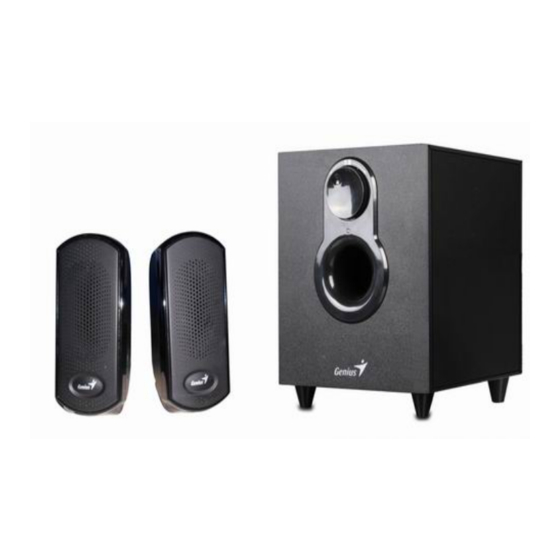
Summary of Contents for KYE Systems Corp. Genius SW-2.1 1000
- Page 1 Service Guide SW-2.1 1000 SERVICE GUIDE KYE SYSTEMS CORP...
-
Page 2: Revision History
Service Guide SW-2.1 1000 Revision History Version Date Change 2011-1-25... -
Page 3: Table Of Contents
Service Guide SW-2.1 1000 Table of Contents Revision History………………………………………………………………….2 Table of contents……………………………………………………………..…3 Getting Start…………………………………………………….………………..4 Conventions Used in this Guide…………………………………………….…...4 Safety Precautions………………………………………………………….……4 Chapter 1. How to Handle Defective Returns………………………………..….5 1.2 Problem………………………………………………………………………6 1.2.1 No power,LED (indicator)unlighted………………………………...7 1.2.2 No sound…………………………………………………………….…….8 1.2.3 Right or left channel no sound….……….……….……….……..….…...…9 1.2.4 Noise………………………………….…………………………..…..…10 1.2.5 LED indicators no light…………………………….….……………...….11 1.2.6 Headphone jack output no sound……………………………..……...…..12... -
Page 4: Getting Start
Service Guide SW-2.1 1000 Getting Started Conventions Used in the Guide Pay Special Attention: Instructions that are important to remember and may prevent mistakes. Caution: Information that, if not followed, may result in damage to the product. Safety Precautions The following precautions should be observed in handing the speaker described in this guide: Place the speakers on a flat, level and stable surface. -
Page 5: Chapter 1 How To Handle Defective Returns
Service Guide SW-2.1 1000 Chapter 1 How to Handle Defective Returns 1.1 Overview Receiving Defective speaker from customers Verifying problems proceeding necessary tests FUNCTION NG Analyzing possible, Main function cause FUNCTION NG FUNCTION OK Deciding & Proceeding the Rectification methods Replace Necessary defective parts Verifying problems... -
Page 6: Problem
Service Guide SW-2.1 1000 1.2 Problems Item Item Problem Description No power,LED (indicator)no light 1.2.1 1.2.2 No sound 1.2.3 Right or left channel no sound 1.2.4 Noise 1.2.5 LED indicator no light 1.2.6 VR, or line-in jack abnormal Attention Please follow the numbered sequence marked within parenthesis given in individual Flow chat in that this is the best-recommended sequence to rectify the problems. -
Page 7: No Power, Led (Indicator) Unlighted
Service Guide SW-2.1 1000 1.2.1 No power, LED (indicator) unlighted Problem No power,LED (indicator)unlighted Analyze Or caused by the following: identify Defective transformer 1. Transformer secondary wire loosely Defective or damaged AC connected with JACK4 jack in SW-2.1 causes cable or power switch 1000 AMPA. -
Page 8: No Sound
Service Guide SW-2.1 1000 1.2.2 No Sound No Sound Problem caused Analyze following defective and identify components the causes short-circuited, JACK5 1. IC1, IC2. IC3, IC4 in dry soldered or board is not properly AMP PCBA broken connected 2. VR1,VR5,JACK4 in SW-2.1 1000 AMP PCBA Solutions... -
Page 9: Right Or Left Channel No Sound
Service Guide SW-2.1 1000 1.2.3 Right or left channel no sound Right or left channel no sound Problem PCB damaged, VR5, JACK2 defective dry-soldered or Driver unit or speaker in SW-2.1 1000 AMP Analyze short-circuited; cable defective PCBA and identify JK1 in SW-2.1 loosely connected the causes... -
Page 10: Noise
Service Guide SW-2.1 1000 1.2.4 Noise Noise Problem Filter capacitor Driver units damaged /diode caused Woofer cabinet leaks, Analyze dry-soldered or vibration from too closed not well and identify damaged, long lead wire of the causes driver units please check C63, C64, C8,... -
Page 11: Led Indicators No Light
Service Guide SW-2.1 1000 1.2.5 LED indicator no light LED indicator no light Problem 1. PCB damaged, dry-soldered or short-circuited 2. R11 in SW-2.1 1000 AMP PCB defective Analyze 3. Poor connection of JACK6 in SW-2.1 1000 PCB and and identify power switch in rear panel the causes 4. -
Page 12: Headphone Jack Output No Sound
Service Guide SW-2.1 1000 1.2.6 VR, or line-in jack abnormal VR, line-in jack abnormal Problem Jack: Defective VR1 may cause JACK2 or JK1 in SW-2.1 Analyze VR5 in 1000 AMP PCBA and identify SW-2.1 1000 AMP PCB or defective the causes VR1/VR5 in Sw-2.1 1000 AMP PCBA having... -
Page 13: Vr, Headphone Jack Or Line-In Jack Abnormal
Service Guide SW-2.1 1000 Chapter 2 Specifications DESCRIPTION channel specification measurement remarks Output Power 1kHz 1﹒ (T.H.D=1%) 1kHz Input Sensitivity 1kHz 2﹒ (T.H.D=1%) 1kHz 1kHz Output Power 3﹒ 1kHz (T.H.D=10%) 100Hz 9..1 1kHz 600±60 Input Sensitivity 4﹒ 1kHz 600±60 (T.H.D=10% 100Hz 130±30 Take 0.5W... -
Page 14: Satellite
Service Guide SW-2.1 1000 Bass=MID 100Hz 0±2 100Hz +6±2 Bass adjustable extent Bass=MAX 100Hz +6±2 100Hz -6±2 Bass adjustable extent Bass=MIN 100Hz -6±2 Treble adjustable extent 10kHz 0±2 Treble=MID 10kHz 0±2 Treble adjustable extent 10kHz +6±2 12﹒ Treble=MAX 10kHz +6±2 Treble adjustable extent 10kHz -6±2... -
Page 15: Chapter 3 Block Diagram
Service Guide SW-2.1 1000 Chapter 3 Block diagram 4588 POWER FILTER UTC2030 POWER AMP SPEAKER SPEAKER... -
Page 16: Chapter 4. Part List
Service Guide SW-2.1 1000 Charter 4 Part List Subwoofer Description Part No. plastic cover 21.4.001.0058 11.1.124.0010 AMP PCBA, SW-2.1 1000 21.1.003.0202 knob 21.4.014.0086 power switch 11.1.192.0003 transformer, 230V/50HZ 10Vx2 11.2.001.0008 woofer driver unit 21.8.040.0042 IC UTC2030(IC1/IC2/IC3) 11.1.170.0017 11.1.171.0036 Power line 11.3.001.0035 11.1.030.0009 Jack1... -
Page 17: Chapter 5 Important Notes
Service Guide SW-2.1 1000 Chart 5 Important notes Packing requirement for sending the PCB assembly by post PCB assembly is a kind of sophisticated electronic circuit board. Well packing will be required when sending them by post. *Some sophisticated IC components are mounted on the PCB assembly; hence it is necessary to pack each PCB assembly with a separate static protecting bag, in order to avoid static electricity. -
Page 18: Chapter 6 Exploded View
Service Guide SW-2.1 1000 Chapter 6 Exploded view Subwoofer... -
Page 19: Left Satellite
Service Guide SW-2.1 1000 Satellites... -
Page 20: Chapter 7 Schematic Diagram
Service Guide SW-2.1 1000 Chapter 7 Schematic diagram...


Need help?
Do you have a question about the Genius SW-2.1 1000 and is the answer not in the manual?
Questions and answers