Table of Contents
Advertisement
Advertisement
Table of Contents

Related Manuals for KYE Systems Corp. Genius SW-HF5.1 5100


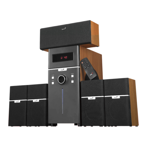
Summary of Contents for KYE Systems Corp. Genius SW-HF5.1 5100
- Page 1 SYSTEMS CORP. SW-HF5.1 5100 V ersion: 1.0 Total 18Pages (Cover page included)
- Page 2 ervice SW-HF5.1 5100 uide Revision History 09/10/2008 Page 1/18 Version: 1.0...
-
Page 3: Table Of Contents
ervice SW-HF5.1 5100 uide Table of Contents Revision History........................1 Table of Contents........................2 Getting Started.........................3 Conventions Used in this Guide................3 Safety Precautions....................3 Chapter 1. How to Handle Defective Returns..............4 1.1 Overview.......................4 1.2 Problems.......................5 1.2.1 No sound and ower LED (indicator) light......6 No response when power on . -
Page 4: Getting Started
ervice SW-HF5.1 5100 uide Getting Started Conventions Used in this Guide Pay Special Attention: Instructions that are important to remember and may prevent mistakes. Attention Caution: Information that, if not followed, may result in damage to the product. Safety Precautions The following precautions should be observed in handling the speaker described in this guide: Place the speakers on a flat, level and stable surface. -
Page 5: Chapter 1. How To Handle Defective Returns
ervice SW-HF5.1 5100 uide Chapter 1. How to Handle Defective Returns 1.1 Overview Receiving Defective Speakers from Customers Verifying problems & proceeding necessary tests Functioning NG Analyzing possible malfunction causes Deciding & proceeding Functioning NG the rectification methods Functioning OK Replacing necessary defective parts Proceeding tests... -
Page 6: Problems
ervice SW-HF5.1 5100 uide 1.2 Problems 1.2.1 No sound and power LED (indicator) unlight No response when power on 1.2.2 1.2.3 LED indicator unlight 1.2.4 One or more channels no sound Page 6/17 Version: 1.0... - Page 7 ervice SW-HF5.1 5100 uide Attention Please follow the numbered sequence marked withing parenthesis given in individual flow chart, in that this is the best-recommended sequence to rectify the problems. 1.2.1 No sound and power LED (indicator) unlight Problem No sound and power LED (indicator) unlight Analyze and Defective...
-
Page 8: No Response When Power On
ervice SW-HF5.1 5100 uide 1.2.2 No response when power on Problem No response when power on Analyze and MCU PCB disconnected Defective SW1,U7(2323) Identify the from amp PCB U6(BT2322) Causes Solutions Resolder or reconnect Replace defective parts MCU PCB OR AMP PCB 1.2.3 LED indicator unlight Problem LED indicator unlight... -
Page 9: One Or More Channel No Sound
ervice SW-HF5.1 5100 uide 1.2.4 One or more channels no sound Problem One or more channels no sound Defective Analyze and U1,U2,U14 Defective Broken or short connection of Identify the BT8974 connection of circuit speaker cable Causes BT9843 audio cable or defective TDA7294 speaker s ( ) -
Page 10: Chapter 2. Specifications
ervice SW-HF5.1 5100 uide Chapter 2. Specifications INPUT SENSITIVITY AT 10% 130 30 400 50 0 50 0 50 ≤1 % ≤1 % ≤1 % ≤1 % OUTPUT POWER AT 10% DISTORTION ≥80 ≥18 ≥13 ≥13 S/N RATIO ≥70 ≥70 ≥70 ≥70 FREQUENCY RESPONSE... -
Page 11: Chapter 3. Block Diagram
SW-HF5.1 5100 ervice uide Chapter 3. Block Diagram AC IN POWER AMPLIFIER CONTROL Page 1 /1 Version: 1.0... -
Page 12: Chapter 4. Exploded View
SW-HF5.1 5100 ervice uide Chapter 4. Exploded View HOST(WOOFER) 21.PIPE 5.LCD LENS 22.PAPER PIPE 23.POWER PCB ASSEMBLE 7.KEY PCB ASSEMBLE 20.HEAT SINK 8.KEY 4.PANEL 24.I/O PCB ASSEMBLE 19.SHEET 9.LIGHT LENS 18.SWITCH 17.FUSE 3.WOOFER ADORN 16.WIRE FIX 10.LED LIGHT 2.VOLUME KNOB 14.SPEAKER 1.KNOB LENS 15.MESH... -
Page 13: Chapter 5 Part List
SW-HF5.1 5100 ervice uide SW-HF5.1 5100 Service Guide Chapter 5 Part List UNIT PartNo. BODY-230V-EU 101166030109 Speaker unit 6.5”8Ω 30W 20280650300402 Speaker unit 3.5” 4Ω 5W 20140350100401 un-antimagnetic speaker unit 3.5”4Ω 5W antimagnetic 20140350100004 speaker unit 0.5”8Ω 10W 20480050100002 301166030009 PCBA Transformer, 412200200109... -
Page 14: Chapter 6. Schematic Diagram
ervice SW-HF5.1 5100 uide Chapter 7. Schematic Diagram Page 1 /1 Version: 1.0... -
Page 15: Chapter 7. Schematic Diagram
ervice SW-HF5.1 5100 uide Chapter 7. Schematic Diagram Page 1 /1 Version: 1.0... -
Page 16: Chapter 8. Schematic Diagram
ervice SW-HF5.1 5100 uide Chapter 7. Schematic Diagram Page 1 /1 Version: 1.0... -
Page 17: Chapter 9. Important Notes
ervice SW-HF5.1 5100 uide Chapter 8. Important Notes 8.1 Packing requirement for sending the PCB assembly by post PCB assembly is a kind of sophisticated electronic circuit board. Well packing will be required when sending them by post. * Some sophisticated IC components are mounted on the PCB assembly, hence it is necessary to pack each PCB assembly with a separate static protecting bag, in order to avoid static electricity.
Need help?
Do you have a question about the Genius SW-HF5.1 5100 and is the answer not in the manual?
Questions and answers