Honeywell E3 Point Quick Start Manual
Hide thumbs
Also See for E3 Point:
- Installation & operation manual (190 pages) ,
- Reference manual (40 pages)
Table of Contents
Advertisement
Available languages
Available languages
Quick Links
E 3 Point Gas Monitor
Quick Start Guide
This guide applies to the E 3 Point ® standalone, network,
and remote monitors. The monitors can be used in indoor
environments such as parking garages, commercial
kitchens, and mechanical rooms among other. An optional
water shield (ECLAB) is also available.
a WARNING
● Power to the E 3 Point monitor must be off during installation and when
installing the sensor cartridge.
● The installer must be grounded for ESD protection while handling the PC
board (PCBA) and during installation of the monitor.
● Follow all local codes when installing the monitor.
● Operate, service, and use the
monitor only as specified in
this quick start guide and the
user manual. Failure to do so
may impair the protection the
monitor is designed to provide
and may also void the warranty.
The manual is available on the
Honeywell Analytics website:
www.honeywellanalytics.com
www.honeywell.com
Scan QR code for manual
● Calibration, set-up, and test modes are intended for use by trained personnel
and service engineers only. Access to these modes can be passcode
protected.
● Follow local and site procedures when working with this monitor. If applicable,
verify that the associated control panel is inhibited in order to prevent false
alarms during installation. The procedures in this quick start guide and the
product's manual must be followed carefully and performed only by trained
personnel and service engineers.
● Use only accessories and parts meeting or exceeding Honeywell Analytics'
specifications.
● Some monitors require warm-up time. See the user manual for specific
information. Do not paint over the monitor screen
● Ensure that the monitor screen is free of dirt and debris.
● Ensure that the monitor screen is not covered.
● Do not expose the monitor to electrical shock and/or continuous mechanical
shock.
The warranty will be voided if the
customer or any unauthorized service
personnel attempt to repair the monitor
a CAUTION
● The E 3 Point monitor must be installed only by trained personnel and service
engineers in accordance with local codes.
● The safety of any system incorporating the E 3 Point monitor is the
responsibility of the assembler of the system.
● Protect the monitor from water, wash-down, and excessive humidity.
● To prevent electrical interference, keep the monitor and wire runs away from
mercury vapor lights, variable speed drives, and radio repeaters.
● Protect the monitor from physical damage (fork lifts, etc.).
● Do not mount the monitor over a door in a refrigerated area.
● For critical locations, more than one monitor should be installed in each room.
● Use caution when opening E3Point or E3Point duct mount enclosures to
avoid damage.
Specifications
Standalone duct or wall mounted gas monitor with optional
additional Remote monitor.
Uses
Network duct or wall mounted gas monitor. Communicates with
301C (or AA96D) at 9600 Baud.
Standalone/Network monitor (H x W x D): 20.56 x 14.90 x 6.72
cm (8.09 x 5.87 x 2.65")
Size
Remote monitor (H x W x D): 3.5 x 4.5 x 6.5 cm (1.36 x 1.75 x
2.56") 38 g (1.34 oz)
Standalone/Network
Remote monitor – Class 2 or
monitor
limited power source (lps) only
24 Vac 350mA 60 Hz
Electro-Chem Sensor: 10 - 24
Electrical
Vdc 50 mA
24 Vdc 350 mA
Ratings
OR
OR
Catalytic Bead Sensor: 10 - 16
E3SAH only - 120 Vac 75
Vdc 100 mA
mA
Electro-Chemical – (CO, NO
, H
S, O
);
2
2
2
Catalytic Bead – (CH
, H
C
H
)
4
2
3
8
Indoor use, Maximum altitude 2000 M, 15 – 80% RH
Sensor
Types and
Response Time:
T90 < 50 seconds;
Operating
with ECLAB (water shield): T90 < 240 seconds
Parameters
All sensors except CO: -40 to 50°C (-40 to 122°F)
CO: -20 to 50°C (-4 to 122°F)
CO for UL 2075: 15 - 35°C (59 - 95°F)
Network monitor
Standalone monitor
1 DPDT relay, 5 A @ 250 Vac
2 DPDT relays, 5 A @ 250
and 30 Vdc
Vac and 30 Vdc
MODbus and BACnet MS/TP
Outputs
4-20 mA
master
Remote monitor – Provides MODbus signal back to
Standalone monitor for processing. 4-20 mA output not
available for Remote monitor. OUT1 and OUT2 are not used.
Display
Standalone/Network monitor – 8 character, 2 line backlit LCD
Standalone monitor
Network monitor
Green LED: Power
Green LED: Power
Visual
Amber LED 1: Alarm/Fault
Amber LED 1: Alarm/Fault
Indicators
Amber LED 2: Alarm/Fault
Amber LED 2: Transmission
Remote monitor – Amber LED: Transmission
Audible
Standalone/Network monitor - > 85 dBA at 3 m (10 ft)
Alarm
Enclosure
Polycarbonate
Safety Requirements For Electrical Equipment For Measurement, Control,
And Laboratory Use - Part 1: General Requirements [UL 61010-1:2012
Ed.3+R:29Apr2016]
Certification
Safety Requirements For Electrical Equipment For Measurement, Control,
And Laboratory Use – Part 1: General Requirements (R2017) [CSA
C22.2#61010-1-12:2012 Ed.3+U1;U2]
Installation
The main installation considerations are height and detection objectives. See the
user manual for guidance.
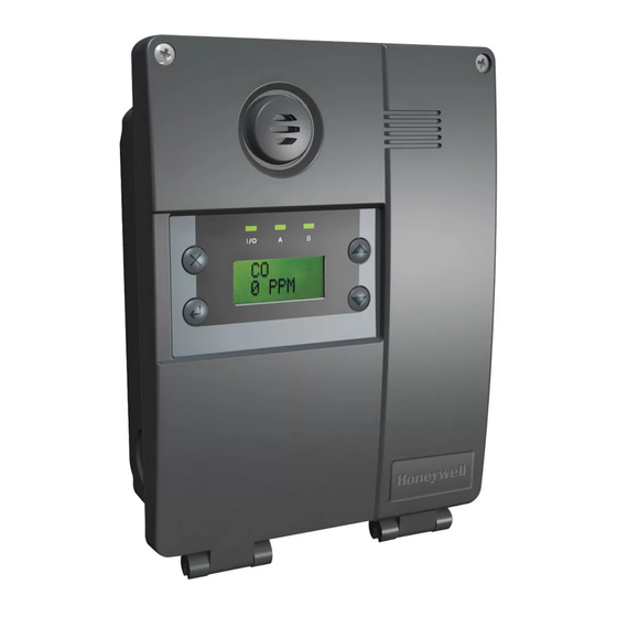
● The monitor must be mounted on a vertical surface, oriented right side up.
When correctly oriented, its control panel will look like this:
Do not mount the monitor flat on a ceiling or on a vibrating surface. Install the
monitor's sensor cartridge only after the enclosure installation is complete.
Wall Mounting for Standalone/Network
monitor
1.
Verify that power to the monitor is off.
2.
While properly grounded for ESD protection, remove the PCBA from
the monitor. It is attached by a single center screw. Carefully place
the PCBA in the enclosed antistatic envelope.
3.
Drill two holes through the case and into the mounting surface;
horizontally if mounting on a vertical surface or vertically if mounting
to a standard electrical box as indicated below.
4.
To mount the monitor, refer to the table for appropriate hardware and
drill size. Use the enclosed mounting template to drill into the vertical
surface if required.
Example
Description
Surface
Part
Rounded head Toggle Bolt
QTY (2)
· 6-32
Drywall, Plaster,
McMaster-Carr
· 3" long
Wood Paneling
#97121A013
· 1-1/2" wingspan toggle
· Pull Out Strength: 35 lbs
Metal Anchor for Block and Brick
QTY (2)
· 1" long
McMaster-Carr
· Pull out Strength: 60 lbs
#97026A021
Block, Brick,
AND
AND
Concrete
Rounded Head Screw
QTY (2)
·No. 6, 7 or 8 sheet metal or wood
McMaster-Carr
screw
#91555A111
· 2" long
Electrical Box
As recommended by the manufacturer of the box or
or Duct
duct
5.
Tighten the mounting bolts or screws to 8.7 in-lb (1 Nm) maximum.
6.
Remove the metal grounding plate before removing knockouts.
7.
Remove one of the knockouts (depending on where cables will enter
the housing) and affix appropriate conduit.
8.
Run wiring through the conduit and the housing to the monitor, (See
Wiring section).
9.
Reinstall the PCBA.
10. Install the sensor cartridge.
11. Complete wiring as shown in the Wiring section.
12. Close the cover and tighten the cover screws to 29.7 in-lb (3 Nm).
13. Restore power to the monitor.
1998-0767
Revision 7
May 2019
Drill
Bit
Size
3/8"
1/4"
N/A
Advertisement
Table of Contents

Related Manuals for Honeywell E3 Point


Summary of Contents for Honeywell E3 Point
- Page 1 Display Standalone/Network monitor – 8 character, 2 line backlit LCD · Pull Out Strength: 35 lbs ● Use only accessories and parts meeting or exceeding Honeywell Analytics’ Standalone monitor Network monitor Metal Anchor for Block and Brick specifications.
- Page 2 9 ppm 150 ppm commissioning Oxygen 0.1%vol 0-25%vol 19.5%vol. 22%vol. 22.5%vol 100%vol Honeywell Analytics Tel: +1 847 955 8200 Hydrogen 0.5% LEL 0-100%LEL 25%LEL 50%LEL 90%LEL 100% LEL System Validation Test or Commissioning of the gas detection 405 Barclay Boulevard...
- Page 3 ● Utilisez uniquement des accessoires et des pièces qui respectent ou 97026A021 · Force de retrait : 60 lb Voyant à DEL ambre 2 : dépassent les spécifications de Honeywell Analytics. Voyant à DEL ambre 2 : (27,22 Kg) Bloc, brique,...
- Page 4 0 à 25 % vol 19,5 % vol 22 % vol 22,5 % vol 0,1 % vol Honeywell Analytics Tél. : +1 847 955 8200 Le test de validation du système et la mise en service du système de détection Hydrogène 0,5 % LEL 0 à...
Need help?
Do you have a question about the E3 Point and is the answer not in the manual?
Questions and answers