Advertisement
12 Clintonville Road
Northford, CT 06472-1610 USA
800-289-3473 • FAX 203-484-7118
www.notifier.com
Overview
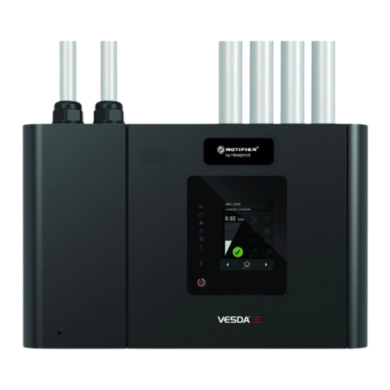
Notifier intelligent VESDA-E VES detectors VES-A00-P-NTF-UL and VES-A10-P-NTF-UL have an integrated Signaling Line Circuit (SLC) mod-
ule to communicate with a Fire Alarm Control Panel (FACP) directly over the SLC loop. The intelligent VES detectors are variants of the conventional
VESDA-E VES detectors with built-in SLC interface module. The VESDA-E VES-A00-P-NTF-UL and VES-A10-P-NTF-UL are UL268, 7th Edition
compliant.
Other than the way they communicate with the FACP, the VESDA-E SLC detectors operate the same as the equivalent conventional detectors. Refer to
the respective conventional detector product guides. (See "Related Product Documents" on page 2.).
NOTE: This product guide describes the specific intelligent VESDA-E features that are different from the respective conventional detectors.
NOTE: For readability, the following terms are used as defined by the product's Installation Instructions:
—"VES-P-NTF-UL" refers to VES-A00-P-NTF-UL and VES-A10-P-NTF-UL
—"VES-P" refers to VES-A00-P and VES-A10-P.
In the case of exceptions, individual models will be specified.
It is essential that anyone using this manual is trained in VESDA-E products and has the knowledge and appropriate certification from the local fire
and electrical authorities.
Codes and standards information for Air Sampling Smoke Detection
We strongly recommend that this document is read in conjunction with the appropriate local codes and standards for smoke detection and electrical
connections. This document contains generic product information and some sections may not comply with all local codes and standards. In these
cases, the local codes and standards take precedence. The information below was correct at the time of printing and may be out of date, check with
your local codes, standards and listings for current restriction.
FCC Compliance Statement
This equipment has been tested and found to comply with the limits for a Class B digital device, pursuant to part 15 of the FCC Rules. These limits are
designated to provide reasonable protection against harmful interference in a residential installation. This equipment generates, uses and can radiate
radio frequency energy and, if not installed and used in accordance with the instruction, may cause harmful interference to radio communications.
However, there is no guarantee that interference will not occur in a particular installation. If this equipment does cause harmful interference to radio or
television reception, the user is encouraged to try to correct the interference by one or more of the following measures: reorient or relocate the
receiving antenna, increase the separation between the equipment and receiver, connect the equipment to a power outlet which is on a different power
circuit to the receiver or consult the dealer or an experienced radio/television technician for help.
FDA
The Xtralis product incorporates a laser device and is classified as a Class 1 laser product that complies with FDA regulations 21 CFR 1040.010. The
laser is housed in a sealed detector chamber and contains no serviceable parts. The laser emits light which can be hazardous to the eye. Under no
circumstances should the detector chamber be opened.
The laser chamber is identified by the labels shown below:
Regional Regulatory Requirements and Notices
UL
Open Area Applications: Covers the applications where users expect nuisance alarm sources such as cooking. Under UL268 7th edition Open Area
Applications, it is specified that a detector is not permitted to signal an alarm in UL-defined "nuisance alarm" conditions.
Special Applications: Covers the applications where very early warning is paramount and users do not expect nuisance alarm sources such as
cooking. Under UL268 7th edition Special Applications, it is specified that a detector is permitted to use higher sensitivity settings, and Open Area
Applications limitations do not apply.
Use of Software Tools (ASPIRE and VSC / VSM4)
The ASPIRE pipe modeling software tool from Xtralis is used to analyze pipework designs to achieve UL compliance. For UL applications explained
above, ASPIRE software is required to design sampling pipe networks that conform to the performance claims verified by UL and listed in Table 1
VESDA-E VES
Product Guide, UL268 7th Edition
PN LS10251-001NF-E:A 7/22/2021 ECN: 00006797
Advertisement
Table of Contents

Related Manuals for Honeywell NOTIFIER VESDA-E VES


Summary of Contents for Honeywell NOTIFIER VESDA-E VES
- Page 1 VESDA-E VES Product Guide, UL268 7th Edition 12 Clintonville Road PN LS10251-001NF-E:A 7/22/2021 ECN: 00006797 Northford, CT 06472-1610 USA 800-289-3473 • FAX 203-484-7118 www.notifier.com Overview Notifier intelligent VESDA-E VES detectors VES-A00-P-NTF-UL and VES-A10-P-NTF-UL have an integrated Signaling Line Circuit (SLC) mod- ule to communicate with a Fire Alarm Control Panel (FACP) directly over the SLC loop.
-
Page 2: Related Product Documents
below. Each sample hole is reported with a transport time and a sensitivity in ASPIRE. Referring to Table 1 below, for UL 268 7th edition compliance the pipework design shall ensure that the: • Transport time for each sampling hole is less than the applicable maximum transport time. •... -
Page 3: Installation
Introduction The VES-NTF-UL model has implemented an interface to communicate with the fire alarm control panel (FACP) over the SLC loop. An interface module mounted to the inside of the VES provides the SLC interface for the detector. The SLC detector does not have VESDAnet capability. Networking is provided by the SLC loop. CAUTION: VESDANET PORT DO NOT CONNECT ANY OTHER DEVICE TO THE SPARE VESDANET PORT ON THE VES-NTF-UL. -
Page 4: Communication Ports
Refer to the diagram below to wire the SLC detector to the FACP. SLC - SLC + FACP + + - - To next Terminal Block on the Interface Module device Communication Ports All standard communication ports on the VES-NTF-UL are available except for VESDAnet. VESDAnet is not available for these models of the detectors. - Page 5 Power The Aspiration device requires 24V DC. The SLC interface is powered from the SLC loop. SLC wiring must be completed to fully power and configure the detector. Device DC Power Supply voltage: 18-30 VDC (24 V Nominal) VES-A00-P-NTF-UL VES-A10-P-NTF-UL Maximum current consumption —Normal Operation: 0.79...
- Page 6 Notes: • Each SLC loop can support a maximum of 31 VES-NTF-UL devices. • Each VES-NTF-UL unit occupies five (5) consecutive addresses on the SLC. – SLC Address 1 through 9 (Group 0): Only one VES-NTF-UL device can be addressed within SLC addresses 1-9. The address field must be set between 1 and 5.
-
Page 7: Configuration Commands
Configuration Commands Refer to the respective VES-UL product guide for detector configuration steps. (See “Related Product Documents” on page 2.) Not all configuration commands defined in VES-UL product guide can be issued using VSC in an SLC interfaced detectors. The following are the commands available using VSC. - Page 8 Referencing Option For the SLC enabled detector, the referencing value is provided by the FACP. When referencing is enabled, the SLC - NFGW should be selected as the reference detector in the VSC software. CAUTION: REFERENCE DETECTOR THE FIRE PANEL MUST NOT USE A VES TYPE OF DETECTOR AS THE REFERENCE DETECTOR. The reference level from the fire panel is subtracted from the smoke level of the VES-UL detector monitoring the protected area.
- Page 9 GPIs and Relays General Purpose Inputs are not available for configuration via the VSC software. Relay options are not configurable via VSC. The following screen shot shows relay assignments for the SLC application. Commissioning Once configured appropriately, ensure the detector can communicate with the FACP without any faults. Refer to respective FACP product guides for configuring the detector over the SLC loop.
-
Page 10: Troubleshooting
Troubleshooting Faults are reported to FACP via the SLC interface in SLC enabled detectors. All of the detector faults are mapped to the following categories at the FACP. Use the Xtralis VSC software to further investigate the fault. – Sensor fault –... -
Page 11: Smoke Test
Smoke Test Test Results Test Method Type of Smoke Test Date Air Sampling Test Results Pipe 1 Pipe 2 Pipe 3 Pipe 4 Transport Time from End Cap Hole Test 1 Initial Response Fire 1 (Alarm) Peak Smoke Test 2 Initial Response Fire 1 (Alarm) Peak Smoke...
Need help?
Do you have a question about the NOTIFIER VESDA-E VES and is the answer not in the manual?
Questions and answers