Table of Contents
Advertisement
Quick Links
Advertisement
Table of Contents
Troubleshooting

Related Manuals for Honeywell BW Technologies GasAlertMicro5


Summary of Contents for Honeywell BW Technologies GasAlertMicro5
- Page 1 1, 2, 3, 4, and 5-Gas Detector User Manual...
-
Page 2: Limited Warranty And Limitation Liability
If any provision of this warranty is held invalid or unenforceable by a court of competent jurisdiction, such holding will not affect the validity or enforceability of any other provision. BW Technologies by Honeywell BW Technologies by Honeywell... -
Page 3: Table Of Contents
Table of Contents Title Page Limited Warranty and Limitation Liability ........................0 Contacting BW Technologies by Honeywell ........................1 Introduction ..................................1 Gases Monitored ................................2 Safety Information - Read First............................2 aCautions ..................................3 Sensor Poisons and Contaminants ..........................6 Getting Started .................................. - Page 4 GasAlertMicro 5/PID/IR User Manual Title Page Deactivating the Detector ..............................20 User Options Menu ................................20 Exit User Options Menu ..............................21 Options Menu................................. 21 Backlight ................................... 22 Confidence Beep ..............................22 Due-Lock .................................. 22 Latched Alarms ................................. 22 Passcode Protect..............................23 Safe Display................................
- Page 5 GasAlertMicro 5/PID/IR User Manual Title Page Bump Daily ................................35 Stealth Mode................................36 Sleep Mode................................36 Alarms ....................................37 Gas Exposures Computed ............................. 40 Viewing Gas Exposures ..............................40 Clearing Gas Exposures ..............................41 Gas Alarm Setpoints ..............................41 Viewing the Alarm Setpoints ............................41 Resetting Gas Alarm Setpoints ............................
- Page 6 GasAlertMicro 5/PID/IR User Manual Title Page Setting the Calibration Due Date ..........................52 Alarm Setpoints ................................ 54 Setting the Remaining Alarm Setpoints ........................56 Finish Calibration ..............................56 Verification ................................56 Unsuccessful Span ..............................57 Attaching the Accessories ............................... 59 Installing the Pump Module............................
- Page 7 GasAlertMicro 5/PID/IR User Manual Title Page Replacing the Alkaline Batteries ............................ 74 Replacing the Lithium Battery Pack ..........................75 Replacing a Sensor or Sensor Filter ..........................75 Photoionization Detector (PID) ............................77 Clean or Replace the Lamp ............................77 Replace the Lamp..............................78 Replace the Electrode Stack ............................
- Page 8 GasAlertMicro 5/PID/IR User Manual Title Page...
- Page 9 List of Figures Figure Title Page Parts of the GasAlertMicro 5/PID/IR........................9 Screen Elements ..............................10 Applying Gas to the Sensors ..........................46 Single Gas Calibration Cap ..........................47 Removing the Single Gas Calibration Cap ......................47 Installing the Pump Module ..........................59 Replacing the Pump Filter ...........................
- Page 10 GasAlertMicro 5/PID/IR User Manual viii...
- Page 11 List of Tables Table Title Page Gases Monitored ..............................2 Sensor Poisons and Contaminants ........................6 International Symbols ............................7 Parts of the GasAlertMicro 5/PID/IR........................9 Screen Elements ..............................10 Pushbutton ................................11 Alarms ................................. 37 Computed Gas Exposures ..........................40 Gas Alarm Setpoints ............................
- Page 12 GasAlertMicro 5/PID/IR User Manual...
-
Page 13: Contacting Bw Technologies By Honeywell
GasAlertMicro 5/PID/IR Contacting BW Technologies by Honeywell Introduction a Warning To contact BW Technologies by Honeywell, call To ensure personal safety, read the Safety Information - USA: 1-888-749-8878 Read First and Cautions before using the detector. Canada: 1-800-663-4164 Europe: +44 (0) 1295 700300... -
Page 14: Gases Monitored
GasAlertMicro 5/PID/IR User Manual Gases Monitored CAUTION: FOR SAFETY REASONS, THIS EQUIPMENT MUST BE OPERATED AND SERVICED BY QUALIFIED PERSONNEL ONLY. The following table lists the gases that are monitored by the detector. READ AND UNDERSTAND THIS USER MANUAL COMPLETELY Table 1. -
Page 15: Acautions
• Do not use the detector if it is damaged. Inspect the detector before using. Look for cracks and/or missing parts. • If the detector is damaged or parts are missing, contact BW Technologies by Honeywell immediately. • Use only sensor(s) that are specifically designed for the GasAlertMicro 5/PID/IR detectors. Refer to Replacement Parts and Accessories. - Page 16 GasAlertMicro 5/PID/IR User Manual aCautions • Any rapid up-scaling reading followed by a declining or erratic reading may indicate a gas concentration beyond upper scale limit, which may be hazardous. • Calibrate only in a safe area that is free of hazardous gas, in an atmosphere of 20.9% oxygen. •...
- Page 17 • Do not attempt to disassemble, adjust, or service the detector unless instructions for that procedure are provided in the user manual and/or that part is listed as a replacement part. Use only BW Technologies by Honeywell Replacement Parts and Accessories.
-
Page 18: Sensor Poisons And Contaminants
Aerosols Lubricants a Caution Brake cleaners Silicone cleaners Bug repellents and protectants and sprays Use only the following BW Technologies by Honeywell recommended products and procedures: Lubricants Silicone based Lubricants adhesives, seal- • Use water based cleaners. ants, and gels •... - Page 19 GasAlertMicro 5/PID/IR Sensor Poisons and Contaminants Table 3. International Symbols Symbol Description Approved to both U.S. and Canadian Standards by CSA International European Explosives Protection Conforms to European Union Directives ATEX Conforms to European ATEX Directives International Electrotechnical Commission Scheme for Certification to Standards for Electrical Equipment for IECEx Explosive Atmospheres...
-
Page 20: Getting Started
GasAlertMicro 5/PID/IR User Manual Getting Started The detector is shipped with the sensors, and battery packs installed. To replace sensors, the pump, or the battery pack, refer to Replacement The list below provides the standard items included with the detector. Parts and Accessories. -
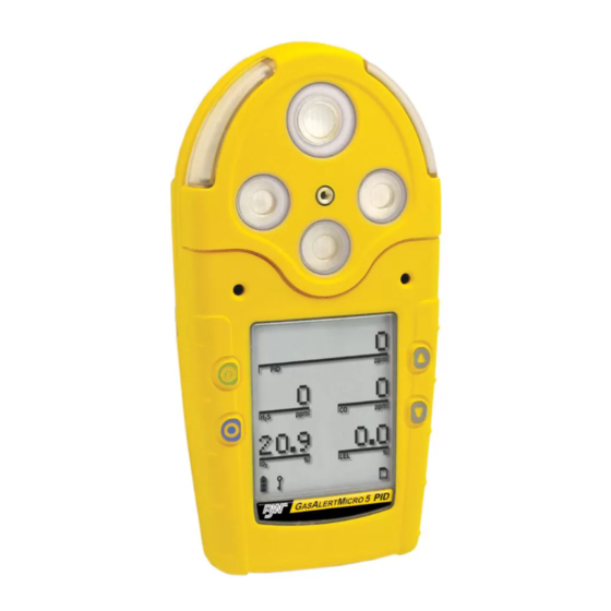
Page 21: Parts Of The Gasalertmicro 5/Pid/Ir
GasAlertMicro 5/PID/IR Parts of the GasAlertMicro 5/PID/IR Parts of the GasAlertMicro 5/PID/IR Table 4. Parts of the GasAlertMicro 5/PID/IR Item Description Liquid crystal display (LCD) Pushbuttons Audible alarms Toxic 2 sensor Toxic 1/PID sensor (Micro 5 PID) Toxic 1/IR (CO ) sensor (Micro 5 IR) Visual alarm indicators (LEDs) LEL sensor... -
Page 22: Screen Elements
GasAlertMicro 5/PID/IR User Manual Screen Elements Table 5. Screen Elements Item Description Alarm condition Automatically span sensor Gas cylinder Gas type Battery life indicator Passcode lock Data transmission Clock Stealth mode Pump indicator (optional) MMC indicator (optional) Alarm condition (low, high, TWA, STEL, or multi alarm) or view TWA, STEL and peak (MAX) gas expo- Figure 2. -
Page 23: Pushbuttons
GasAlertMicro 5/PID/IR Pushbuttons Pushbuttons Table 6. Pushbutton Pushbutton Description • To activate the detector press A. • To deactivate the detector, press and hold A until the countdown is complete. • To increment the displayed value or scroll up, press G. •... -
Page 24: Activating The Detector
GasAlertMicro 5/PID/IR User Manual Activating the Detector Battery Test If using the pump module, attach it and the pump accessories prior to The detector performs a battery test during startup. If the battery has activating the detector. insufficient power to operate, the following screen displays before deactivating. -
Page 25: Datalogging (Optional)
GasAlertMicro 5/PID/IR Activating the Detector 2. The version and serial number of the detector displays. Note If there is a problem with the MMC/SD card, Datalogger disabled displays. The detector then automatically continues with the self-test. If the card requires formatting, the following screen displays as the card is automatically formatted. - Page 26 GasAlertMicro 5/PID/IR User Manual Self-test Successful: If successful, the following screen displays. 7. The TWA, STEL, low, and high alarm setpoints then display in the following order (left to right). STEL Self-test Unsuccessful: If a sensor fails the self-test, a warning displays indicating which sensor(s) has failed.
-
Page 27: Pump Test
GasAlertMicro 5/PID/IR Activating the Detector Pump Test If the pump inlet is not blocked within 10 seconds or the pump test fails, the following screens display. 8. If the pump module is attached to the detector, the following screens display. If C is not pressed or the pump is not removed within 25 seconds, the detector performs the pump test again. -
Page 28: Due-Lock Enabled
GasAlertMicro 5/PID/IR User Manual 9. Unless disabled in user options, the oxygen (O ) sensor is cali- If any sensor is over due for calibration, the LCD displays the name of the sensor and the number of days past due. brated automatically. -
Page 29: Force Calibration Enabled
GasAlertMicro 5/PID/IR Activating the Detector If no passcode is entered, or it is entered incorrectly, the follow- ing screen displays. Bump Daily Enabled a Caution To enable/disable this option, refer to Due-Lock in the user BW recommends that a bump test to all sensors be options menu. - Page 30 GasAlertMicro 5/PID/IR User Manual Successful Bump Test: If the bump test passes, the following screens If additional sensors require a bump test but are not mandatory, the display. following screens display. Press C Yes to accept and proceed to normal operation. The detector waits for the sensor(s) to clear (30 seconds) and then enters normal operation.
-
Page 31: Self-Test Pass
GasAlertMicro 5/PID/IR Activating the Detector Self-Test Pass Battery Test If the detector passes the self-test, it enters normal operation and The batteries are tested when the detector is activated and continuously displays the ambient gas readings. thereafter. The battery power icon displays continually during normal operation. -
Page 32: Deactivating The Detector
GasAlertMicro 5/PID/IR User Manual Deactivating the Detector User Options Menu To deactivate the detector, press and hold A while it beeps and flashes If the detector is passcode protected, a passcode must be entered to to the corresponding countdown. access the user options menu. For more information, refer to Passcode Protect. -
Page 33: Exit User Options Menu
GasAlertMicro 5/PID/IR User Options Menu 1. To enter the user options menu, press and hold G and H Note simultaneously as the detector beeps and flashes to the cor- If no pushbuttons are pressed within 20 seconds, the detector responding countdown. returns to normal operation. -
Page 34: Backlight
GasAlertMicro 5/PID/IR User Manual Backlight Due-Lock The Backlght (backlight) option enables If the Due-lock (calibration user lockout) the LCD backlight to activate automatically option is enabled and a sensor is overdue in low-light conditions. for calibration upon startup, the passcode must be entered to access normal opera- If disabled, the backlight activates only tion. -
Page 35: Passcode Protect
GasAlertMicro 5/PID/IR User Options Menu Passcode Protect Safe Display The Passcode option prevents unauthorized When enabled, the Safe option confirms that access to the user options menu, the calibra- conditions are normal and there are no gas tion function, and to adjusting the alarm hazards present. -
Page 36: Sensor Configuration
GasAlertMicro 5/PID/IR User Manual Sensor Configuration 1. From the option menu screen, scroll to Sensors and press C to access the following screen. The Sensor option provides access to additional options and functions for each sensor. Depending upon the sensor that is selected, some or all of the following options are available for configuration: •... -
Page 37: Sensor Enable/Disable
GasAlertMicro 5/PID/IR User Options Menu Sensor Enable/Disable If disabled, the readings and the gas type for the sensor do not display when in normal operation. a Warning If a sensor is enabled but it is not installed in the detector, FAIL flashes Disabling a sensor should only be performed with above the gas type of the missing sensor. -
Page 38: Span Gas Value
GasAlertMicro 5/PID/IR User Manual Span Gas Value STEL Period The Span gas option increases or The short-term exposure limit (STEL period) option provides decreases the gas concentration for protection for workers from over exposure to high concentrations calibration (must match the gas of gas, and is based on 5-15 minute intervals. -
Page 39: Twa Method
GasAlertMicro 5/PID/IR User Options Menu TWA Method Resolution The TWA method (time-weighted average) The Resolution option displays the gas option is a safety measure used to calculate measurement using Regular or Extra accumulated averages of gases to notify the resolution. user when the maximum average is Regular: Displays gas measurement in accumulated. -
Page 40: Vol Co 2 (Co 2 Sensors Only)
GasAlertMicro 5/PID/IR User Manual %Vol CO Sensors Only) %Vol CH (LEL Sensors Only) If the %vol CO is enabled, the detector If %vol CH is enabled, any currently displays the carbon dioxide (CO enabled correction factor is ignored and the detector operates assuming a readings as %vol (0.0). - Page 41 GasAlertMicro 5/PID/IR User Options Menu LEL Sensor PID Sensor This option is used to enter compensation This option is used to enter compensation factors for hydrocarbons other than factors for selected gas types. The factor methane. The factor can only be applied if can only be applied if the PID sensor has the LEL sensor has been calibrated with been calibrated with isobutylene.
-
Page 42: Automatic Oxygen (O 2 ) Calibration
GasAlertMicro 5/PID/IR User Manual Automatic Oxygen (O ) Calibration Logger Option The Logger option is used to define how often the detector records a When the Autocal option is enabled, it datalog sample (once every 1 to 127 seconds). forces the detector to automatically From the user options menu, press H to scroll to Logger. -
Page 43: Clock Option
GasAlertMicro 5/PID/IR User Options Menu If C is not pressed within 5 seconds, the following screen displays. The screen displays showing the month highlighted indicating it is selected to set. The detector is shipped with the datalog sample time set to 5 seconds. Press G or H to scroll to the desired month and press C within Clock Option 20 seconds to confirm. -
Page 44: Language Selection
GasAlertMicro 5/PID/IR User Manual Language Selection Wait for 20 seconds until the detector returns to the user options menu, or press G to scroll to Back (English), Retour (French), Zurück The detector is shipped with English selected as the default language. (German), Regreso (Spanish), or Retornar (Portuguese). -
Page 45: Sensors
GasAlertMicro 5/PID/IR User Options Menu In the following order, press and continue to hold each button until Sensors Tech mode displays below the Language option. a Caution 1. Press and hold H with the right index finger. To reconfigure the sensor type, physically change the sensor prior to entering Tech mode. -
Page 46: Initialize
GasAlertMicro 5/PID/IR User Manual A corresponding list of toxic sensors Initialize displays. A checkbox displays beside The Initialize option restores the origi- the current toxic sensor. nal factory default settings of the detec- tor. Note Press H to scroll to Initialize and Toxic 1: List includes the PID and CO press C within 20 seconds to sensors. -
Page 47: Force Calibration
GasAlertMicro 5/PID/IR User Options Menu Bump Daily If Yes is selected, the following screen displays while performing the initializing If enabled, the Bmp daily option forces the process. detector to perform a daily bump test to ensure that it is responding to the test gas. Press H to scroll to Bmp daily. -
Page 48: Stealth Mode
GasAlertMicro 5/PID/IR User Manual Stealth Mode Sleep Mode Note The Stealth option disables the backlight, visual alarms, and audible alarms when BW recommends the Sleep option be enabled when using concealment is required. rechargeable battery packs. Only the vibrator and the LCD activate If Sleep is enabled, sensor circuits remain during an alarm condition. -
Page 49: Alarms
GasAlertMicro 5/PID/IR Alarms Alarms The following table describes the detector alarms and corresponding screens. • During an alarm condition, the detector activates the backlight and displays the current ambient gas reading. • If more than one type or level of alarm exists simultaneously, a multi alarm results. •... - Page 50 GasAlertMicro 5/PID/IR User Manual Table 7. Alarms Alarms Screen Alarms Screen Multi Alarm Over Limit (OL) Exposure Alarm • Alternating low and high alarm • Fast beep and flash beep and flash • and gas type flash • and gas types flash •...
- Page 51 GasAlertMicro 5/PID/IR Alarms Table 7. Alarms Alarms Screen Alarms Screen Confidence Beep MMC/SD Fail Alarm • One beep, one flash, and one • One beep every 5 seconds vibrate every 10 seconds • S flashes Alarms Screen Pump Alarm • Two fast beeps and alternating flashes •...
-
Page 52: Gas Exposures Computed
GasAlertMicro 5/PID/IR User Manual Gas Exposures Computed Viewing Gas Exposures a Warning Press and hold C until the peak (MAX) gas exposures To avoid possible personal injury, do not deactivate the detector during a work shift. TWA and STEL readings displays. -
Page 53: Clearing Gas Exposures
GasAlertMicro 5/PID/IR Alarms Clearing Gas Exposures Table 9. Gas Alarm Setpoints The exposures automatically clear after 5 minutes when the detector Alarm Condition is deactivated. To clear the MAX, TWA, and STEL exposure readings immediately, Low alarm Toxics and combustibles: Ambient press and hold C and G simultaneously. -
Page 54: Resetting Gas Alarm Setpoints
GasAlertMicro 5/PID/IR User Manual The time/date, TWA, STEL, low, and high alarm setpoint screens display Resetting Gas Alarm Setpoints in the following order left to right:. Note Standard factory alarm setpoints may vary by region. The following table lists the factory alarm setpoints according to the Occupational Safety and Health Association (OSHA) settings. -
Page 55: Stopping A Gas Alarm
GasAlertMicro 5/PID/IR Alarms To change the factory-set alarm setpoints, refer to Calibration and Set- Sensor Alarm ting Alarm Setpoints. The detector tests for missing or defective sensors during the activation Note self-test. If a sensor fails the self-test, FAIL flashes on the LCD above the failed sensor. -
Page 56: Low Battery Alarm
GasAlertMicro 5/PID/IR User Manual Calibration and Setting Alarm Setpoints Refer to Pump Test for more information. If the pump test is successful, the detector returns to normal operation, otherwise the pump alarm con- tinues. If the pump alarm persists, refer to the Pump Operation section in Guidelines Troubleshooting. -
Page 57: Diagnostics Testing
• After activating the detector, allow it to stabilize for 1 minute before performing a calibration or bump test. • If a certified calibration is required, contact BW Technologies by Honeywell. Note A generator must be used for O and ClO... -
Page 58: Applying Gas To The Sensors
GasAlertMicro 5/PID/IR User Manual Applying Gas to the Sensors Table 11. Applying Gas to the Sensors The calibration cap, single gas calibration cap, and hose are shipped Item Description with the detector. Refer to Figure 3. Table 11. for installation. Detector with calibration cap Note Calibration hose... -
Page 59: Calibration Procedure
GasAlertMicro 5/PID/IR Calibration and Setting Alarm Setpoints Table 12. Single Gas Calibration Cap Removing the Single Gas Calibration Cap Using the thumb, push forward against both the inlet and the outlet Item Description simultaneously to remove the cap from the detector. Intake inlet Calibration hose Gas flow direction arrow... -
Page 60: Start Calibration
GasAlertMicro 5/PID/IR User Manual Start Calibration GasAlertMicro 5/PID GasAlertMicro 5 IR Note Verify that the calibration gas being used matches the span concentration value(s) that are set for the detector. Refer to Span Gas Value. Correction factors are not applied during cali- bration. -
Page 61: Passcode Protect Activated
GasAlertMicro 5/PID/IR Calibration and Setting Alarm Setpoints Press C Yes to zero the CO sensor. flashes whiles the detector zeros the CO sensor (approximately 30 seconds). Passcode Protect Activated Press A No to bypass the CO zero and proceed to Auto Span step #5. -
Page 62: Auto Span
GasAlertMicro 5/PID/IR User Manual Auto Span Note A generator must be used for O and ClO sensors. 5. When auto zero is complete, the following screens display. To ensure accurate calibration, a single gas calibration cap GasAlertMicro 5 and PID must be used to calibrate O and ClO sensors. - Page 63 GasAlertMicro 5/PID/IR Calibration and Setting Alarm Setpoints K flashes as the detector initially detects the calibration gas. While the detector is spanning the sensor(s), a countdown of time remaining displays in the lower left of the screen. GasAlertMicro 5 and PID GasAlertMicro 5 IR GasAlertMicro 5 and PID GasAlertMicro 5 IR...
-
Page 64: Successful Span
GasAlertMicro 5/PID/IR User Manual Successful Span Setting the Calibration Due Date 6. If the sensor(s) has spanned successfully, the audible alarm 7. When the span is complete, the calibration due date can be set beeps three times and the following screens display. for each sensor that has spanned successfully. - Page 65 GasAlertMicro 5/PID/IR Calibration and Setting Alarm Setpoints The calibration due dates are set in the following order: Note If a value is changed but C is not pressed within 5 seconds to • Toxic 1 confirm, the following screen displays. •...
-
Page 66: Alarm Setpoints
GasAlertMicro 5/PID/IR User Manual Alarm Setpoints If a new setpoint is entered but not confirmed within 5 seconds by pressing C, the following screen displays. 8. When all of the sensor due dates have been set or bypassed, the alarm setpoints need to be set or bypassed. The following screen displays. - Page 67 GasAlertMicro 5/PID/IR Calibration and Setting Alarm Setpoints Setting the TWA Alarm Setpoint Setting the Low Alarm Setpoint The current TWA alarm setpoint displays for the selected sensor The current low alarm setpoint displays for the selected sensor. (if applicable). Press H or G to change the value for the low alarm setpoint. When the Press H or G to change the value for the TWA alarm setpoint.
-
Page 68: Setting The Remaining Alarm Setpoints
GasAlertMicro 5/PID/IR User Manual Setting the Remaining Alarm Setpoints Verification 9. Repeat step #8 to set the alarm setpoints for the remaining 1. After calibration is complete and the detector returns sensors. When complete, the detector emits two quick beeps to normal operation, verify the calibration by using a and proceeds to Finish... -
Page 69: Unsuccessful Span
GasAlertMicro 5/PID/IR Calibration and Setting Alarm Setpoints Unsuccessful Span If all sensors fail the span, the following screen displays. If the sensor(s) did not span successfully, refer to the following sections for possible solutions: • Failed Span • No Gas Detected •... - Page 70 GasAlertMicro 5/PID/IR User Manual No Gas Detected Not reaching the target span can result from If the detector does not detect any gas within 30 seconds, the following • a problem with the span gas, screens display. • the gas cylinder being past the expiry date, or •...
-
Page 71: Attaching The Accessories
GasAlertMicro 5/PID/IR Attaching the Accessories Attaching the Accessories Table 14. Installing the Pump Module Item Description Installing the Pump Module Pump module The pump module can be used independently to measure gas or it can Sensor filter be used with the sample probe to test for gases in confined spaces. To Detector measure gas using the sample probe, refer to Attaching the Sample... -
Page 72: Replacing The Pump Filter
Accessories. a Caution Filters may need to be replaced more frequently in high particulate areas. BW Technologies by Honeywell recommends that the auxiliary filter be used as a additional filtration in high particulate areas. Figure 7. Replacing the Pump Filter... -
Page 73: Replacing The Pump Nozzle
GasAlertMicro 5/PID/IR Attaching the Accessories Replacing the Pump Nozzle 3. Insert the new nozzle. Ensure the nozzle post inserts correctly into the nozzle gasket. To replace the pump nozzle, refer to Figure 8. and step 1-4. 4. Activate the detector. The detector performs a pump test dur- ing the startup self-tests to verify the pump module is operating correctly. - Page 74 GasAlertMicro 5/PID/IR User Manual a Caution Note Attaching the filter cord to the alligator clip ensures the filter The filter is designed to protect the pump. For older model pumps, the filter must be connected when the remains with the detector when not in use. pump is activated.
-
Page 75: Attaching The Sample Probe
GasAlertMicro 5/PID/IR Attaching the Accessories a Caution Attaching the Sample Probe To prevent the Teflon lining inside the Tygon tubing from The sample probe is used to safely test for gas in confined spaces causing a blockage when connecting it to the sample before entering. -
Page 76: Datalogger
GasAlertMicro 5/PID/IR User Manual Datalogger MMC/SD Card Compatibility a Caution Detectors equipped with the datalogger option record information that can be compiled to create a report. To set how often the detector records To ensure the Intrinsic Safety rating of the detector, use a sample (1-127 seconds), refer to Logger Option in the user options... -
Page 77: Mmc/Sd Card Troubleshooting
GasAlertMicro 5/PID/IR MMC/SD Card Troubleshooting 5. Activate the detector. The MMC/SD card is automatically for- MMC/SD Card Troubleshooting matted during the startup self-test. The MMC/SD card is not required for operation in detectors equipped with datalogging. However, the following two screens display if the card is not inserted during startup. -
Page 78: Restoring Datalog Files
GasAlertMicro 5/PID/IR User Manual Restoring Datalog Files If the detector successfully restores the logfile, the following screen displays and the startup tests continue. If the MMC/SD card has been accidentally reformatted or erased by the computer application, the following screens display when the card is inserted into the detector. -
Page 79: Reformatting The Mmc/Sd Card
GasAlertMicro 5/PID/IR MMC/SD Card Troubleshooting 7. Press G to format the MMC/SD card. The following screen dis- Reformatting the MMC/SD Card plays. To reformat the MMC/SD card, complete the following: 1. Insert the MMC/SD card into the card reader. 2. From the computer desktop, double-click My Computer to view the list of drives. -
Page 80: Import Datalogs To Fleet Manager Ii
GasAlertMicro 5/PID/IR User Manual Import Datalogs to Fleet Manager II Import to Fleet Manager II Using a Card Reader Note To import a datalog file from the detector to Fleet Manager II, complete the following: Refer to the following minimum requirements before importing datalogs to Fleet Manager II. -
Page 81: View Datalog Files In Spreadsheets
GasAlertMicro 5/PID/IR View Datalog Files in Spreadsheets View Datalog Files in Spreadsheets The datalog files can be downloaded from the MMC/SD card into most spreadsheet applications using a card reader. Compatible software applications are • Microsoft® Excel 98 or higher, •... -
Page 82: Example Of A Datalog Spreadsheet
GasAlertMicro 5/PID/IR User Manual Example of a Datalog Spreadsheet When datalog information is imported into most spreadsheet software, it appears similar to the example below. a Warning: Some compatible software packages have an internal file size limit and may not load the entire file. Check the software limit. Note Not all columns are included in this example. - Page 83 GasAlertMicro 5/PID/IR View Datalog Files in Spreadsheets Table 16. Datalog Status Codes Status Codes ⎯ Normal operation Backlight is on Low alarm STEL and high alarm (dual alarms) Alarm setpoint 1 (low alarm) High alarm TWA and STEL alarm (dual alarms) Alarm setpoint 2 (high alarm) TWA alarm TWA, STEL, and low (triple alarms)
- Page 84 GasAlertMicro 5/PID/IR User Manual Table 17. Datalog Gas and Correction Factor Sensor Codes Gas Sensor Codes No sensor S COSH CO COSH Correction Factor Codes for PID (if applicable) Acetaldhyde Acetone Ammonia Benzene Butadiene Diesel Ethanol Ethylene Gasoline Hexane Isobtyln Kerosene Naptha Styrene...
-
Page 85: Maintenance
Spent batteries must be disposed of by a qualified recycler or hazardous materials handler. • Use only batteries that are recommended by BW Technologies by Honeywell. Refer to Specifications. • Keep lithium cells away from children. • Ensure the alkaline batteries are properly installed in the detector battery pack. -
Page 86: Replacing The Alkaline Batteries
GasAlertMicro 5/PID/IR User Manual Replacing the Alkaline Batteries Table 18. Replacing the Alkaline Batteries To replace the alkaline batteries, refer to Figure 13., Table 18., and the Item Description following steps 1-6. Detector Latch Battery pack Battery tray Captive screws (2) Alkaline batteries (3) Battery shell 1. -
Page 87: Replacing The Lithium Battery Pack
GasAlertMicro 5/PID/IR Maintenance Replacing the Lithium Battery Pack 1. Open the latch on the bottom of the detector. 2. Remove the battery pack by lifting the bottom of the pack To replace the lithium battery pack, refer to Figure 14. and the following upward from the detector. - Page 88 GasAlertMicro 5/PID/IR User Manual To replace a sensor or sensor filter, refer to Figure 15., Table 19., and Table 19. Replacing a Sensor or Sensor Filter the following procedures 1-7. Item Description Sensor cover Sensor filter Sensors Detector Machine screws (2) 1.
-
Page 89: Photoionization Detector (Pid)
Clean or Replace the Lamp The PID lamp must be cleaned regularly. Use only the cleaning kit that is supplied by BW Technologies by Honeywell. To clean the PID lamp, refer to the illustrations and procedures that are provided with the PID Lamp Cleaning Kit. To order the kit, refer Replacement Parts and Accessories. -
Page 90: Replace The Lamp
To replace the lamp, refer to the illustrations and procedures in the the stack. PID Lamp Cleaning Kit. 1. Remove the sensor cover. If required, contact BW Technologies by Honeywell for more information. 2. Remove the old electrode stack. 3. Insert the new electrode stack. 4. Replace the sensor cover. -
Page 91: Troubleshooting
GasAlertMicro 5/PID/IR Troubleshooting Troubleshooting If a problem occurs, refer to the solutions provided in Table 21.. If the problem persists, contact BW Technologies by Honeywell. Table 21. Troubleshooting Problem Possible Cause Solution Startup Troubleshooting The detector does not No batteries... - Page 92 GasAlertMicro 5/PID/IR User Manual Table 21. Troubleshooting Problem Possible Cause Solution Detector Operation Troubleshooting Detector does not display Sensor not stabilized Used sensor: wait 60 seconds normal ambient gas New sensor: wait 5 minutes readings after startup Detector requires calibration Calibrate the sensors.
- Page 93 Retry communication communication with the MMC/ Insert a new approved MMC or SD card. Refer to Inserting the MMC/SD SD card. Card. Reformat the MMC or SD card in windows and then reinsert into the detector. Contact BW Technologies by Honeywell.
- Page 94 GasAlertMicro 5/PID/IR User Manual Table 21. Troubleshooting Problem Possible Cause Solution Alarms Troubleshooting Detector does not enter Alarm setpoint(s) are set Reset alarm setpoints. Refer to Calibration and Setting Alarm Setpoints. alarm mode. incorrectly. Alarm setpoint(s) are set to Reset alarm setpoints. Refer to Calibration and Setting Alarm Setpoints.
- Page 95 LEL reading displaying as 2. From the Pump Speed screen, press H to decrease the speed to 150. over limit (OL). 3. Exit user options. The detector automatically initiates a pump test. 4. If the pump alarm persists, contact BW Technologies by Honeywell.
- Page 96 Possible Cause Solution Clock Errors Troubleshooting Clock icon is flashing. The clock has failed. Contact BW Technologies by Honeywell. There is communication failure. Contact BW Technologies by Honeywell. The detector displays a General fault. Reactivate the detector. If the same error message displays, reset the clock clock error message using in the user options menu.
-
Page 97: Replacement Parts And Accessories
Dummy sensor 3-pin O or TwinTox SR-DUMM1 To order parts or accessories, contact BW Technologies by Honeywell. SR-DUMM2 Dummy sensor for LEL location Table 22. Replacement Parts and Accessories Sensor Replacement Parts and Accessories RL-PID10.6... - Page 98 GasAlertMicro 5/PID/IR User Manual CG2-M-200-103 Calibration gas, CO 200 ppm (103 l) Datalogger Accessories Calibration gas, SO 25 ppm (58 l) CR-MMC-USB1 USB memory card reader CG2-S-25-58 MMC128-D 128 MB Delkin MMC Calibration gas, Cl 5 ppm (58 l) CG2-C-5-58 MMC128-D 128 MB Delkin SD card CG2-Z-10-58...
-
Page 99: Specifications
GasAlertMicro 5/PID/IR Specifications Specifications : 0 – 5.0 ppm (0.1 ppm increments) : 0 – 150 ppm (1 ppm increments) Instrument dimensions: 14.5 x 7.4 x 3.8 cm (5.7 x 2.9 x 1.5 in.) : 0 – 50.0 ppm (0.1 ppm increments) Weight: 370 g (13.1 oz.) : 0 –... - Page 100 GasAlertMicro 5/PID/IR User Manual Backlight: Automatically activates during an alarm condition and when Battery operating time: there is insufficient light to view the LCD (if enabled in user options) Toxic, O , and LEL sensors: Three alkaline cells or one lithium battery Self-test: Initiated during activation pack at 20°C provides 20 hours operating runtime Toxic, O...
- Page 101 GasAlertMicro 5/PID/IR Specifications Approvals: This equipment has been tested and found to comply with the limits for a Class B digital device, pursuant to Part 15 of the FCC Rules and GasAlertMicro 5 and GasAlertMicro 5 PID (Zone 0) ICES-003 Canadian EMI requirements. These limits are designed to Approved by CSA to both U.S.
-
Page 102: General Specifications For Datalogger Units
GasAlertMicro 5/PID/IR User Manual General Specifications for Datalogger Units GasAlertMicro 5/PID/IR Downloadable Datalogger Media type: MultiMediaCard (MMC) or Secure Digital (SD) card Operation: Requires no user intervention (automatic) Approved MMC and SD cards for GasAlertMicro 5 and Indicators: Icon indicates datalogger is operating normally, MMC/SD GasAlertMicro 5 PID: 128 MB Delkin SD card and 64 MB Unigen SD card missing/malfunction card... -
Page 103: Pid Correction Factor (Cf) Library
GasAlertMicro 5/PID/IR PID Correction Factor (CF) Library PID Correction Factor (CF) Library Table 23. PID Corrections Factor (CF) Library Correction Factor Value Gas # Gas Type LCD Gas Type Abbreviation (CF values subject to change) No PID correction factor Acetaldehyde Acetdhd 4.6’... - Page 104 GasAlertMicro 5/PID/IR User Manual...
- Page 105 iERP: 128900 D5615/5 [English] © BW Technologies 2009. All rights reserved.
Need help?
Do you have a question about the BW Technologies GasAlertMicro5 and is the answer not in the manual?
Questions and answers