Table of Contents
Advertisement
Quick Links
www.ti.com
User's Guide
TLVM13660 36-V, 6-A Buck Regulator Evaluation Module
User's Guide
With an input operating voltage range from 3 V to 36 V and rated output current from 2 A to 6 A, the
TLVM13620, TLVM13630, TLVM13640, and TLVM13660 family of synchronous buck power modules outlined
in
Table 1-1
provides flexibility, scalability, and optimized solution size for a wide range of applications. With
intergrated power MOSFETs, buck inductor, and PWM controller, these modules enable DC/DC solutions with
high density, low EMI, and increased flexibility. Available EMI mitigation features include RBOOT-configured
switch-node slew rate control and integrated capacitors for the high-frequency switching loops. All modules are
rated for ambient and junction temperatures up to 105°C and 125°C, respectively.
Table 1-1. TLVM13620, TLVM13630, TLVM13640, and TLVM13660 Synchronous Buck DC/DC Power
DC/DC Module
Rated I
OUT
TLVM13620
2 A
TLVM13630
3 A
TLVM13640
4 A
TLVM13660
6 A
The
TLVM13660EVM
uses the TLVM13660 – a compact, easy-to-use synchronous buck module IC with a wide
output voltage range of 1 V to 6 V and an output current up to 6 A. The default output voltage of the EVM is 5 V
and is adjustable using jumper settings to the following output voltages as needed:
•
1.2 V
•
1.8 V
•
2.5 V
•
3.3 V
The solution supports adjustable input voltage UVLO for application-specific power-up and power-down
requirements, a PGOOD indicator for sequencing and output voltage monitoring, and integrated VIN, VCC,
and CBOOT capacitors for low EMI signature.
SLVUCF7 – MARCH 2022
Submit Document Feedback
ABSTRACT
Module Family
Package
Dimensions
B0QFN (30)
6.0 × 4.0 × 1.8 mm
B3QFN (20)
5.5 × 5.0 × 4.0 mm
Copyright © 2022 Texas Instruments Incorporated
Features
RT adjustable F
, PGOOD
SW
indicator, external bias
option, inverting buck-boost
(IBB) capability
TLVM13660 36-V, 6-A Buck Regulator Evaluation Module User's Guide
EMI Mitigation
Integrated input, VCC and CBOOT
capacitors
Integrated input, VCC and CBOOT
capacitors; slew-rate control
1
Advertisement
Table of Contents

Subscribe to Our Youtube Channel
Related Manuals for Texas Instruments TLVM13660


Summary of Contents for Texas Instruments TLVM13660
-
Page 1: Table 1-1. Tlvm13620, Tlvm13630, Tlvm13640, And Tlvm13660 Synchronous Buck Dc/Dc Power Module Family
TLVM13660EVM uses the TLVM13660 – a compact, easy-to-use synchronous buck module IC with a wide output voltage range of 1 V to 6 V and an output current up to 6 A. The default output voltage of the EVM is 5 V and is adjustable using jumper settings to the following output voltages as needed: •... -
Page 2: Table Of Contents
Figure 5-29. CISPR 32 Class B Radiated Emissions: Horizontal Polarization................Figure 5-30. CISPR 32 Class B Radiated Emissions: Vertical Polarization................14 TLVM13660 36-V, 6-A Buck Regulator Evaluation Module User's Guide SLVUCF7 – MARCH 2022 Submit Document Feedback Copyright © 2022 Texas Instruments Incorporated... - Page 3 Figure 6-7. Bottom Layer Copper (Viewed From Top)....................... Figure 6-8. Top Assembly (Top View)............................Figure 6-9. Bottom Assembly (Bottom View)..........................List of Tables Table 1-1. TLVM13620, TLVM13630, TLVM13640, and TLVM13660 Synchronous Buck DC/DC Power Module Family...1 Table 2-1. Electrical Performance Specifications.........................5 Table 4-1.
-
Page 4: High-Density Evm Description
1 High-Density EVM Description TLVM13660EVM features the TLVM13660 synchronous buck power module configured for operation with typical 3-V to 36-V input bus applications. This wide-V range DC/DC solution offers outsized voltage rating and operating margin to withstand supply-rail voltage transients. -
Page 5: Evm Performance Specifications
D = |V | / (V + |V |) is the duty cycle. SLVUCF7 – MARCH 2022 TLVM13660 36-V, 6-A Buck Regulator Evaluation Module User's Guide Submit Document Feedback Copyright © 2022 Texas Instruments Incorporated... -
Page 6: Evm Photo
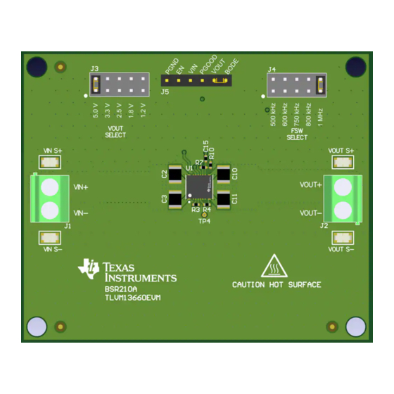
16-AWG wire thickness. Figure 3-1. TLVM13660 EVM Photo CAUTION Caution Hot surface. Contact may cause burns. Do not touch. TLVM13660 36-V, 6-A Buck Regulator Evaluation Module User's Guide SLVUCF7 – MARCH 2022 Submit Document Feedback Copyright © 2022 Texas Instruments Incorporated... -
Page 7: Test Setup And Procedure
4-1, use the recommended test setup in Figure 4-1 to evaluate the TLVM13660. Working at an ESD-protected workstation, make sure that any wrist straps, bootstraps, or mats are connected and referencing the user to earth ground before power is applied to the EVM. -
Page 8: Evm Setup
TLVM13660 Quickstart Calculator WEBENCH ® Power Designer for additional guidance pertaining to module setup and component selection. TLVM13660 36-V, 6-A Buck Regulator Evaluation Module User's Guide SLVUCF7 – MARCH 2022 Submit Document Feedback Copyright © 2022 Texas Instruments Incorporated... -
Page 9: Test Equipment
Review the thermal performance plots for more detail. SLVUCF7 – MARCH 2022 TLVM13660 36-V, 6-A Buck Regulator Evaluation Module User's Guide Submit Document Feedback Copyright © 2022 Texas Instruments Incorporated... -
Page 10: Test Data And Performance Curves
= –5 V, Figure 5-5. Load and Line Regulation, V = 5 V, = 1 MHz = 1 MHz TLVM13660 36-V, 6-A Buck Regulator Evaluation Module User's Guide SLVUCF7 – MARCH 2022 Submit Document Feedback Copyright © 2022 Texas Instruments Incorporated... -
Page 11: Waveforms
Figure 5-11. Bode Plot with Four 47-µF, 10-V, X7R Output Figure 5-12. Output Capacitance vs. Voltage Derating Curve Capacitors (100 µF Effective at 5 VDC, 25°C) SLVUCF7 – MARCH 2022 TLVM13660 36-V, 6-A Buck Regulator Evaluation Module User's Guide Submit Document Feedback Copyright © 2022 Texas Instruments Incorporated... -
Page 12: Thermal Performance
= 24 V, V = 2.5 V, = 6 A, F = 500 kHz = 6 A, F = 500 kHz TLVM13660 36-V, 6-A Buck Regulator Evaluation Module User's Guide SLVUCF7 – MARCH 2022 Submit Document Feedback Copyright © 2022 Texas Instruments Incorporated... -
Page 13: Figure 5-19. Thermal Derating Curve: V
Figure 5-24. Thermal Derating Curve: V = 24 V, V = 2.5 V, = 500 kHz = 500 kHz SLVUCF7 – MARCH 2022 TLVM13660 36-V, 6-A Buck Regulator Evaluation Module User's Guide Submit Document Feedback Copyright © 2022 Texas Instruments Incorporated... -
Page 14: Emi Performance
Figure 5-29. CISPR 32 Class B Radiated Figure 5-30. CISPR 32 Class B Radiated Emissions: Horizontal Polarization Emissions: Vertical Polarization TLVM13660 36-V, 6-A Buck Regulator Evaluation Module User's Guide SLVUCF7 – MARCH 2022 Submit Document Feedback Copyright © 2022 Texas Instruments Incorporated... -
Page 15: Evm Documentation
EVM Documentation 6 EVM Documentation 6.1 Schematic Figure 6-1 illustrates the EVM schematic. Figure 6-1. EVM Schematic SLVUCF7 – MARCH 2022 TLVM13660 36-V, 6-A Buck Regulator Evaluation Module User's Guide Submit Document Feedback Copyright © 2022 Texas Instruments Incorporated... -
Page 16: List Of Materials
Test point, miniature, SMT — 5019 Keystone — TLVM13660 36-V, 6-A buck power module B3QFN20 TLVM13660RDLR Texas Instruments TLVM13660 36-V, 6-A Buck Regulator Evaluation Module User's Guide SLVUCF7 – MARCH 2022 Submit Document Feedback Copyright © 2022 Texas Instruments Incorporated... -
Page 17: Pcb Layout
The PCB is 62-mils standard thickness with 2-oz copper on all layers. Figure 6-2. 3D Top View Figure 6-3. 3D Bottom View SLVUCF7 – MARCH 2022 TLVM13660 36-V, 6-A Buck Regulator Evaluation Module User's Guide Submit Document Feedback Copyright © 2022 Texas Instruments Incorporated... -
Page 18: Figure 6-4. Top Layer Copper
EVM Documentation www.ti.com Figure 6-4. Top Layer Copper Figure 6-5. Layer 2 Copper TLVM13660 36-V, 6-A Buck Regulator Evaluation Module User's Guide SLVUCF7 – MARCH 2022 Submit Document Feedback Copyright © 2022 Texas Instruments Incorporated... -
Page 19: Figure 6-6. Layer
EVM Documentation Figure 6-6. Layer 3 Copper Figure 6-7. Bottom Layer Copper (Viewed From Top) SLVUCF7 – MARCH 2022 TLVM13660 36-V, 6-A Buck Regulator Evaluation Module User's Guide Submit Document Feedback Copyright © 2022 Texas Instruments Incorporated... -
Page 20: Assembly Drawings
EVM Documentation www.ti.com 6.4 Assembly Drawings Figure 6-8. Top Assembly (Top View) Figure 6-9. Bottom Assembly (Bottom View) TLVM13660 36-V, 6-A Buck Regulator Evaluation Module User's Guide SLVUCF7 – MARCH 2022 Submit Document Feedback Copyright © 2022 Texas Instruments Incorporated... -
Page 21: Multi-Layer Stackup
FR-4 High Tg Bottom Layer Signal Copper Bottom Solder Solder Mask/Coverlay Surface Material Solder Resist Bottom Overlay Overlay SLVUCF7 – MARCH 2022 TLVM13660 36-V, 6-A Buck Regulator Evaluation Module User's Guide Submit Document Feedback Copyright © 2022 Texas Instruments Incorporated... -
Page 22: Device And Documentation Support
36-V, 6-A synchronous buck module 7.1.1.1 Custom Design With WEBENCH® Tools Click here to create a custom design using the TLVM13660 device with WEBENCH® Power Designer. 1. Start by entering the input voltage (V ), output voltage (V ), and output current (I ) requirements. - Page 23 STANDARD TERMS FOR EVALUATION MODULES Delivery: TI delivers TI evaluation boards, kits, or modules, including any accompanying demonstration software, components, and/or documentation which may be provided together or separately (collectively, an “EVM” or “EVMs”) to the User (“User”) in accordance with the terms set forth herein.
- Page 24 www.ti.com Regulatory Notices: 3.1 United States 3.1.1 Notice applicable to EVMs not FCC-Approved: FCC NOTICE: This kit is designed to allow product developers to evaluate electronic components, circuitry, or software associated with the kit to determine whether to incorporate such items in a finished product and software developers to write software applications for use with the end product.
- Page 25 www.ti.com Concernant les EVMs avec antennes détachables Conformément à la réglementation d'Industrie Canada, le présent émetteur radio peut fonctionner avec une antenne d'un type et d'un gain maximal (ou inférieur) approuvé pour l'émetteur par Industrie Canada. Dans le but de réduire les risques de brouillage radioélectrique à...
- Page 26 www.ti.com EVM Use Restrictions and Warnings: 4.1 EVMS ARE NOT FOR USE IN FUNCTIONAL SAFETY AND/OR SAFETY CRITICAL EVALUATIONS, INCLUDING BUT NOT LIMITED TO EVALUATIONS OF LIFE SUPPORT APPLICATIONS. 4.2 User must read and apply the user guide and other available documentation provided by TI regarding the EVM prior to handling or using the EVM, including without limitation any warning or restriction notices.
- Page 27 Notwithstanding the foregoing, any judgment may be enforced in any United States or foreign court, and TI may seek injunctive relief in any United States or foreign court. Mailing Address: Texas Instruments, Post Office Box 655303, Dallas, Texas 75265 Copyright © 2019, Texas Instruments Incorporated...
- Page 28 TI products. TI’s provision of these resources does not expand or otherwise alter TI’s applicable warranties or warranty disclaimers for TI products. TI objects to and rejects any additional or different terms you may have proposed. IMPORTANT NOTICE Mailing Address: Texas Instruments, Post Office Box 655303, Dallas, Texas 75265 Copyright © 2022, Texas Instruments Incorporated...
Need help?
Do you have a question about the TLVM13660 and is the answer not in the manual?
Questions and answers