Sign In
Upload
Manuals
Brands
Texas Instruments Manuals
Control Unit
TLVM13630
Texas Instruments TLVM13630 Manuals
Manuals and User Guides for Texas Instruments TLVM13630. We have
1
Texas Instruments TLVM13630 manual available for free PDF download: User Manual
Texas Instruments TLVM13630 User Manual (28 pages)
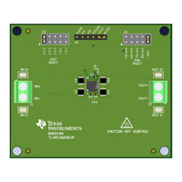
36-V, 6-A Buck Regulator Evaluation Module
Brand:
Texas Instruments
| Category:
Control Unit
| Size: 2 MB
Table of Contents
Table 1-1. TLVM13620, TLVM13630, TLVM13640, and TLVM13660 Synchronous Buck DC/DC Power Module Family
1
Table of Contents
2
1 High-Density EVM Description
4
Typical Applications
4
Features and Electrical Performance
4
2 EVM Performance Specifications
5
Table 2-1. Electrical Performance Specifications
5
3 EVM Photo
6
Figure 3-1. TLVM13660 EVM Photo
6
4 Test Setup and Procedure
7
EVM Connections
7
Figure 4-1. EVM Test Setup
7
Table 4-1. EVM Power Connections
7
Table 4-2. EVM Signal Connections
7
EVM Setup
8
Test Equipment
9
Recommended Test Setup
9
Test Procedure
9
5 Test Data and Performance Curves
10
Efficiency and Load Regulation Performance
10
Figure 5-1. Efficiency
10
Figure 5-2. Efficiency
10
Figure 5-3. Efficiency
10
Figure 5-4. Efficiency, VOUT
10
Out
10
V, Fsw
10
Figure 5-5. Load and Line Regulation, V
10
Figure 5-6. Load and Line Regulation, V
10
Bode Plot
11
Figure 5-10. Load Transient, 3 a to 6 a at
11
Figure 5-11. Bode Plot with Four 47-Μf, 10-V, X7R Output Capacitors (100 Μf Effective at 5 VDC, 25°C)
11
Figure 5-12. Output Capacitance Vs. Voltage Derating Curve
11
Figure 5-7. Start-Up
11
Figure 5-8. Shutdown
11
Figure 5-9. Enable on and off
11
Waveforms
11
Figure 5-13. Infrared Thermal Image: V
12
Figure 5-14. Infrared Thermal Image
12
Figure 5-15. Infrared Thermal Image
12
Figure 5-16. Infrared Thermal Image
12
Figure 5-17. Infrared Thermal Image
12
Figure 5-18. Infrared Thermal Image: V
12
Thermal Performance
12
Figure 5-19. Thermal Derating Curve: V
13
Figure 5-20. Thermal Derating Curve: V
13
Figure 5-21. Thermal Derating Curve: V
13
Figure 5-22. Thermal Derating Curve: V
13
Figure 5-23. Thermal Derating Curve: V
13
Figure 5-24. Thermal Derating Curve: V
13
EMI Performance
14
FSW = 1 Mhz
14
Figure 5-25. CISPR 32 Class B Conducted Emissions
14
Figure 5-26. CISPR 32 Class B Conducted Emissions
14
Figure 5-27. CISPR 32 Class B Conducted Emissions
14
Figure 5-28. CISPR 32 Class B Conducted Emissions: VIN = 24 V, VOUT = 3.3 V, FSW = 750 Khz
14
Figure 5-29. CISPR 32 Class B Radiated Emissions: Horizontal Polarization
14
Out = 2.5 V, Fsw in
14
Figure 5-30. CISPR 32 Class B Radiated Emissions: Vertical Polarization
14
6 EVM Documentation
15
Schematic
15
Figure 6-1. EVM Schematic
15
List of Materials
16
Table 6-1. Component List of Materials
16
PCB Layout
17
Figure 6-2. 3D Top View
17
Figure 6-3. 3D Bottom View
17
Figure 6-4. Top Layer Copper
18
Figure 6-5. Layer
18
Figure 6-6. Layer
19
Figure 6-7. Bottom Layer Copper (Viewed from Top)
19
Assembly Drawings
20
Figure 6-8. Top Assembly (Top View)
20
Figure 6-9. Bottom Assembly (Bottom View)
20
Multi-Layer Stackup
21
Table 6-2. Layer Stackup
21
7 Device and Documentation Support
22
Device Support
22
Documentation Support
22
Webench
22
Advertisement
Advertisement
Related Products
Texas Instruments TLVM13660
Texas Instruments TLVM13620
Texas Instruments TLVM13640
Texas Instruments TLV5540
Texas Instruments TLV5510
Texas Instruments TLV320AIC3109EVM-K
Texas Instruments TLV320DAC26EVM
Texas Instruments TLV320AIC3268EVM-U
Texas Instruments TLV9061
Texas Instruments TLC694 Series
Texas Instruments Categories
Motherboard
Control Unit
Microcontrollers
Computer Hardware
Calculator
More Texas Instruments Manuals
Login
Sign In
OR
Sign in with Facebook
Sign in with Google
Upload manual
Upload from disk
Upload from URL