
Related Manuals for R&M LK10C022200


Summary of Contents for R&M LK10C022200
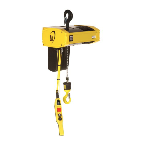
- Page 1 English Original instructions OWNER'S MANUAL FOR CHAIN HOIST LK10C022200 101106635 - 1911-012-JB_Updated - 01602417990010-0.ORD 01.10.2020...
-
Page 2: Table Of Contents
Table of contents GENERAL INTRODUCTION ......................5 Foreword: About this Manual ......................... 5 Symbols Used in this Manual ......................... 5 Safety Alert Symbols and Signal Words ......................5 Questions and Comments ..........................6 Exclusion of Warranty ............................ 6 Manual Use ..............................6 Environmental Information .......................... - Page 3 5.2.2 Adjusting pendant cable length ......................43 5.2.3 Connecting hoist to power supply ......................44 COMMISSIONING ........................... 45 Commissioning preparations ........................46 Checks before first run ..........................47 Before lifting ..............................49 Test run without load ............................ 50 Test run with test load ..........................53 After test runs ...............................
- Page 4 APPENDIX: DESIGNED WORKING PERIOD (DWP) CALCULATION ..........109 ANNEX: ANSI HAND SIGNALS ......................112 APPENDIX: RECONNECTABLE HOIST ....................113 APPENDIX: REPLACING THE CONTROL VOLTAGE FUSE .............. 115 CERTIFICATES .......................... 116 11.1 Load chain ..............................116 11.2 Lower hook .............................117 EC DECLARATION OF CONFORMITY ....................118 4/118 This document and the information contained herein, is the exclusive property of R&M Materials Handling Inc.
-
Page 5: General Introduction
GENERAL INTRODUCTION Foreword: About this Manual This manual offers guidance to enable safe and efficient operation of the equipment. Taking the time to read this manual will help you to prevent damage to the equipment, and, most importantly, personnel situated close to it. The equipment is designed to be safe when used correctly. However, there are many potential hazards associated with incorrect operation and these can be avoided when you know how to recognize and anticipate them. -
Page 6: Questions And Comments
INDICATES AN IMMINENTLY HAZARDOUS SITUATION WHICH, IF NOT DANGER AVOIDED, WILL RESULT IN DEATH OR SERIOUS INJURY. Addresses situations not related to personal injury, such as likely or possible damage NOTICE to equipment. Shall Indicates that a rule is mandatory and must be followed. Should Indicates that a rule is a recommendation, the advisability of which depends on the facts in each situation. -
Page 7: Environmental Information
not limited to the Owner’s or READER’S use thereof or any other cause identified herein or that may be reasonably inferred HEREFROM. Environmental Information Environmental aspects have been taken into account in designing and manufacturing this product. To prevent environmental risks during use, please follow instructions for safe lubricant handling and disposal of waste material. Proper use and maintenance improves environmental performance of this product. -
Page 8: Terminology
Terminology The following terms and definitions are used in this manual: ANSI American National Standards Institute International Organization for Standardization Authorized personnel Persons who are authorized by the owner and who have the necessary training to carry out operation or service actions. Experienced service person authorized by A person with service experience who is authorized by the manufacturer to perform service the manufacturer... -
Page 9: Safety First
SAFETY FIRST! Safety requirements must be understood and followed. Personal Protective Equipment (PPE) Note: This chapter proposes personal protective equipment to ensure operator’s full safety. Local regulations and requirements of the working environment shall be followed. For safety, the operator or others in close proximity to the product may be required to wear Personal Protective Equipment (PPE). -
Page 10: Fall Protection
2.1.1 Fall protection While personnel are performing inspection or maintenance work at heights, they must follow fall protection procedures as required by local regulations. Fall prevention practices and fall protection equipment aim to protect personnel working on or around the equipment from exposure to falls. If the equipment does not have a service platform or handrail, personnel must use a properly fitted safety harness that is attached to the dedicated fixing points on the building or equipment in order to prevent falls. -
Page 11: Main Isolation Switch
Main Isolation Switch The product can only be driven when power is turned on. The owner must identify and document the location and function of the main isolation switch and must communicate this information to all operators. Owner/Operator shall be aware of main isolation switch functionality. Even though one switch is turned off, there may still be voltage present in some CAUTION parts of the product. -
Page 12: Owner's Responsibilities
Owner’s Responsibilities 2.5.1 General Safety Issues No modifications or additions to the equipment structures or performance values are permitted unless they are first discussed with and approved by the CAUTION manufacturer or manufacturer’s representative of the equipment. Modifying the equipment without the manufacturer or manufacturer’s representative approval can invalidate the guarantee. - Page 13 Do not allow the equipment to be used unless it is in proper condition. In case of doubt, contact a service agent authorized by the manufacturer or WARNING manufacturer’s representative! The use of defective equipment can result in serious damage, injury or death. Keep the product in a safe condition Owners SHALL ensure that the equipment is kept in a safe condition.
-
Page 14: Hoisting Machinery Designed Working Period (Dwp)
2.5.2 Hoisting machinery designed working period (DWP) Based on how the hoisting machinery will be used and on the actual hoisting machinery hardware supplied, the manufacturer will agree the anticipated hoisting machinery lifetime or designed working period (DWP) with the customer at the time of purchase. -
Page 15: Intended Use Of The Product
Intended use of the product The product for general use is an entity which has been designed to perform common lifting, traveling and lowering operations, within the limits specified by the product’s duty group (see chapter Duty group). The hoisting machinery for general use must not be modified or used for any other purpose without the written approval of the manufacturer. -
Page 16: Duty Group
2.6.1 Duty group When the product is designed and purchased, the predicted lifetime of the product is agreed, based on the expected use of the product. This expected use is known as the duty group. Hoisting machinery which is used continuously to lift heavy loads is clearly in a very different duty group to a product of the same size which is used occasionally just to lift light loads. -
Page 17: Operating Environment
The number of work cycles per hour and the average lifted loads. Authorized service personnel must periodically check whether the product is being used according to the duty group. Owners and operators should recognize that any changes to product usage could, if left unchecked, raise overall maintenance costs and considerably reduce the safe operating lifetime of the product. -
Page 18: Safety During Installation
Safety during installation Ensure the competence of installation personnel Owners SHALL ensure that installation personnel are professionally competent, professionally qualified and are provided with adequate instructions for carrying out the work. Ensure proper commissioning and handover Owners SHALL ensure that the test loading, test drive, and commissioning inspection have been properly executed. - Page 19 Ensure that the support structure is prepared for the product Owners must ensure that the support structure which the product is attached to is designed for the load of the product and meets the specific requirements and tolerances. Check the power supply is compatible Check that the supply voltage and frequency match the requirements of the product.
-
Page 20: Safety During Usage
Safety during Usage This chapter only presents the owner’s responsibilities towards the operator with regard to equipment usage. See instructions for the operator for detailed safety information concerning actual usage of the equipment. Operator training Owners SHALL ensure that operators are properly trained. Operators must know how to operate the equipment safely before starting to work with the equipment. - Page 21 Inform that equipment will be undergoing maintenance Before starting maintenance, people must be properly informed that the equipment is being removed from operation. Ensure that there is no load on the lifting device Before starting maintenance there should be no load on the hook or lifting device. Park the hook on the ground if there is any chance that the hoisting brake will be opened during maintenance.
-
Page 22: Lockout - Tagout Procedure
Returning the product to operation after overload or collision After an overload or collision incident, the appropriate inspection and repair operations must be discussed with the supplier of the product. Pay special attention to all safety-critical components The brakes, limit switches, hook, chain and controller are all safety-critical items which must always be kept in good order. -
Page 23: Sound Intensity Level
2.11 Sound Intensity Level Hoists generate some audible noise during operation. The total noise level experienced in the operating area is a combination of the individual noise sources around the operator. The main sources of noise from the hoist arise from its components, vibrating structures and reflective surfaces. -
Page 24: Identification
IDENTIFICATION Hoist identification data 3.1.1 Hoist data plate for CE-labeled hoist The hoist serial number is stated on the hoist data plate that can be found on the hoist body. Figure 1. CE data plate for hoist Brand Brand logo Product type Designation of the machinery in English Product type... - Page 25 Power of hoisting motor Power output of the hoisting motor Trolley type Type of the trolley used in the product Traveling speed Highest and lowest traveling speed Rated input of traveling motor Rated input of current to the traveling motor in amperes Power of traveling motor Power output of the traveling motor Electrical information...
-
Page 26: Hoist Data Plate For Csa-Labeled Hoist
3.1.2 Hoist data plate for CSA-labeled hoist The hoist serial number is stated on the hoist data plate that can be found on the hoist body. Figure 2. CSA data plate for hoist Brand Brand logo Product type Designation of the machinery in English Product type Designation of the machinery in the selected language Serial number... - Page 27 Rated input of traveling motor Rated input of current to the traveling motor in amperes Power of traveling motor Power output of the traveling motor Electrical information Rated input in main voltage, control voltage, frequency, number of phases (1 or 3 phases) Fuse Rating of the fuse for the main power supply Manufacturing date...
-
Page 28: Motor Identification Data
Motor identification data 3.2.1 Traveling motor Motor data plate Product identification data Bar code sticker Product order references Motor type code Exact model of the product Motor number Unique number which identifies the unit Acceptable main voltage range and frequency of the power source that the product can be Input connected to Output... -
Page 29: Manufacturer
Manufacturer R&M Materials Handling Inc. Manufacturer: 4501 Gateway Boulevard Address: 45502 SPRINGFIELD, OH Note: For further information about the product, operational training or servicing, please contact the closest representative of the manufacturer. Standards and directives This state of the art product has been designed and manufactured to conform to European and international standards and directives. -
Page 30: Construction
CONSTRUCTION Identifying key parts of the hoist Pos. Part Description Hoisting machinery Equipment composed of hoist frame, hoisting motor, gear and brake Hook Composed of hook and hook block Suspension hook The upper hook with which hook-suspended hoist is fixed to its support structure Chain bucket Bucket where the lifting chain is gathered and stored Controller... - Page 31 Pos. Part Description Hoisting machinery Composed of hoist frame, hoisting motor, gear, and brake Hook Composed of hook and hook block Traveling machinery Composed of traveling motor, gear, and brake Electrical cubicle for trolley movement Electrical control system for trolley drive Trolley Composed of trolley frame and traveling wheels (traveling limit switch optional) Chain bucket...
-
Page 32: Main Functions
Main Functions 4.2.1 Hoisting function Main components of electrical chain hoist hoisting function Pos. Part Main power board Main contactor Hoisting gear Motor board Hoisting brake (single brake in the example) Friction torque limiter Hoisting motor Sprocket wheel 32/118 This document and the information contained herein, is the exclusive property of R&M Materials Handling Inc. and represents a non-public, confidential and proprietary trade secret that may not be reproduced, disclosed to third parties, altered or otherwise employed in any manner whatsoever without the express written consent of R&M Materials Handling Inc. -
Page 33: How The Hoisting Function Works
4.2.2 How the hoisting function works KINEMATIC CHAIN FOR ELECTRICAL CHAIN HOIST Pos. Part Adjustment screw Gear Chain sprocket Motor Friction torque limiter Brake Motor torque Brake torque Motor torque path The motor (4) rotates the axle, which makes the hoisting gear (2) helical steps turn. The gear transfers the motor power over the chain sprocket (3) to the hoisting chain, which then moves according to the selected direction (up or down). -
Page 34: Traveling Function
Brake torque path The brake (6) is always electrically disengaged when the motor (4) works. As soon the motor stops, the brake engages and blocks the rotation of the hoisting gear components and the chain sprocket. Only use the emergency stop button to stop the movement in the event of a malfunction or another emergency situation. -
Page 35: Safety Functions
Only use the emergency stop button to stop movement in the event of malfunction or NOTICE other emergency situation. Using the emergency stop button can cause the load to swing unexpectedly. 4.2.2 Safety Functions Hoisting unit Device Description Emergency stop button The emergency stop button is used to turn off power to the system in dangerous situations. -
Page 36: Safety Signs
4.3.1 Safety Signs Safety signs inform the operator about potential hazards and also about special features concerning the product’s operation. Failure to avoid dangers identified by these signs can result in death or serious injury. Sign Description Location on product Danger of electric shock On electric cubicle and other cubicles. -
Page 37: Installation
INSTALLATION Before installation, read the instructions in chapter Safety first. Installation procedure requires special skills (qualified personnel) and tools* (e.g. the clutch adjustment tool ChainQ and chain inserting tool) to ensure safe and reliable operation of the product. Installation work shall be carried out only by authorized service personnel or an experienced service technician authorized by the product’s manufacturer. -
Page 38: Installation Preparations
Installation preparations The product is packed in a box for transportation. Before starting to install the hoist, visually check that the package in which the product has been delivered to you is intact. Also check that the content of the delivery matches with your order. -
Page 39: Fitting The Chain Bucket
5.1.1 Fitting the chain bucket If the chain bucket joint hinge is not already pre-attached, Attach the chain bucket to the hinge and secure the fix it to the hoist enclosure with screws. connection with the locking pin and the nut. If the hoist has been stored for a long time or has been transported by sea, check that the motors are dry. - Page 40 Never attempt to lift a load before ensuring that it weighs less than the maximum permitted load of the auxiliary lifting devices. Overloading can WARNING damage the auxiliary lifting devices. Lifting points Hook or eye-suspended models Motorized trolley or push trolley Lift the hoist from suspension hook Lift the hoist from trolley side plates 40/118...
-
Page 41: Electrical Connections
Electrical connections Only a qualified electrician may make any electrical connections. The electrical connections must be made according to the wiring diagrams that are provided with the product. The power supply must be OFF and locked before making any electrical connections. -
Page 42: Installing Pendant Cable
5.2.1 Installing pendant cable Remove the four screws that hold the cover plate in Leave the cover plate hanging from the strip. place. Disconnect the power supply plug from the power supply Slide the power cable assembly out. It is put back in place socket. -
Page 43: Adjusting Pendant Cable Length
5.2.2 Adjusting pendant cable length Cut the wires of socket so that you have a model on how Open the cable gland and peel the wires off from the wires are connected to the socket. length needed. Cut the cable to selected length and peel the wires. Tighten the cable gland (1) and shorten the retaining wire (2). -
Page 44: Connecting Hoist To Power Supply
5.2.3 Connecting hoist to power supply The hoist is delivered with a short (temporary) power Place the main power supply cable through the cable supply cable that is attached to the power socket. gland and the cable entry to the connector and connect Remove the cable from the socket and open the cable the wires to the plug. -
Page 45: Commissioning
COMMISSIONING Note: Before handing over the equipment, proper commissioning shall be done. The required inspections and adjustments are listed in the chapters concerning the installation and commissioning of the hoist. The equipment shall not be used before proper commissioning. The commissioning procedure requires special skills and tools to ensure safe and reliable operation of the equipment. -
Page 46: Commissioning Preparations
Commissioning preparations During installation, commission and maintenance, lockout-tagout procedures must be followed in accordance with local regulations and the documented site lockout-tagout policy. See chapter Lockout-Tagout procedure. Ensure that there are no hazards from loose items Items which are not properly secured to the product, such as tools or detached components, could move or fall accidentally, with potentially serious consequences. -
Page 47: Checks Before First Run
Checks before first run Lubrication The hoist is delivered with an unlubricated chain. The initial lubrication is part of the commissioning preparations of a new hoist. Lubricate the chain carefully before taking the hoist into use for the first time. See instructions in chapter Lubrication instructions for the chain. NOTE: Failing to do the initial lubrication of the chain leads to premature wear of the chain and the complete chain drive. - Page 48 AN IMPROPER OR INSUFFICIENT GROUND CONNECTION CREATES AN ELECTRICAL SHOCK HAZARD WHEN TOUCHING ANY PART OF THE HOIST OR TROLLEY. IN THE POWER SUPPLY CABLE, THE GROUNDING WIRE IS EITHER GREEN WITH YELLOW STRIPE OR SOLID GREEN. IT SHOULD DANGER ALWAYS BE CONNECTED TO A SUITABLE GROUND CONNECTION.
-
Page 49: Before Lifting
Before lifting Check that the load is balanced and safely fastened at the lifting points. The load must not be able to slide, slip or detach itself when suspended. When you begin to lift, check that the load is properly balanced before lifting it high off the ground. -
Page 50: Test Run Without Load
Test run without load Electrical connections Turn on the power to the hoist. Controller Check that the controller is correctly installed and in good condition. If you have a radio controlled hoist,check that the radio controller does not cause any disturbance to other radio controlled equipment. - Page 51 Hoisting limit switch Mechanical limit switch Check the operation of the upper and lower mechanical limit switch. Drive the hook upwards until the upper mechanical limit switch is activated and prevents further upward movement of the hook. If the limit switch operates correctly, it stops the motor without activating the friction torque limiter when the limit is reached.
- Page 52 Any defects or abnormalities which are detected during the commissioning must be investigated and corrected in accordance with the instructions CAUTION relevant to the component in question. Trolley Run the trolley at least 3…5 times over the whole length of the girder. Check that the trolley moves smoothly.
-
Page 53: Test Run With Test Load
Test run with test load The test load must be securely fastened and properly balanced. Static and dynamic tests The equipment is to be tested with dynamic tests with 110 % of the nominal load and static tests with 125 % of the nominal load. Make sure that the hook does not turn around while lifting. - Page 54 Local requirements may demand other commissioning testing to be performed before NOTICE the product can be used. Make sure all the local requirements are fulfilled. All optional features must be tested before using the product. 54/118 This document and the information contained herein, is the exclusive property of R&M Materials Handling Inc. and represents a non-public, confidential and proprietary trade secret that may not be reproduced, disclosed to third parties, altered or otherwise employed in any manner whatsoever without the express written consent of R&M Materials Handling Inc.
-
Page 55: After Test Runs
After test runs Visual check Check visually that the hoist or any other part has not been damaged in any way during commission testing. Cleaning Check that all tools and materials used during installation are removed from the hoist and the track. -
Page 56: Instructions For The Operator
INSTRUCTIONS FOR THE OPERATOR Operator’s Responsibilities Hoists are used for various purposes, handle different types of loads and are operated different ways by many operators. Many workers, as part of their regular job responsibilities, normally operate hoists as non-dedicated operators. Because the manufacturer of the hoist has no direct involvement or control over the hoist’s operation and application, conforming to good safety practices is the responsibility of the owner, and the equipment’s operating personnel. - Page 57 Operators SHALL learn the hand signals for directing equipment’s movements. Operators SHALL be familiar with proper rigging procedures. Operators SHALL carry out daily inspections Always follow the local regulations. Operators SHALL NOT: Operators SHALL NOT operate the equipment when under the influence of alcohol or drugs. Alcohol and drugs can impair judgment and thereby cause a hazard.
-
Page 58: Control Devices And Their Location
Control devices and their location 7.2.1 Controls for movements The speed corresponds to the position of the direction control. The equipment moves at the slowest speed when the pushbutton is partially pushed and at the maximum speed when the pushbutton is fully pushed. The equipment stops moving when the pushbutton is released. - Page 59 Operating a product with an abnormal condition or malfunction can result in WARNING serious injury or death or serious damage to the product. 59/118 This document and the information contained herein, is the exclusive property of R&M Materials Handling Inc. and represents a non-public, confidential and proprietary trade secret that may not be reproduced, disclosed to third parties, altered or otherwise employed in any manner whatsoever without the express written consent of R&M Materials Handling Inc.
-
Page 60: Checks To Be Performed By The Operator
7.3.1 Checks to be performed by the operator Check the general condition Visually check the of the hoist. operating environment to make sure that there are no new hazards which might prevent the safe use of the product. Visually check to see if there Visually check the chains are any oil leaks from the for any deformation,... -
Page 61: Operational Checks With The Emergency Stop Button Pushed Down
7.3.2 Operational Checks with the Emergency Stop Button Pushed Down Turn on the main power isolation switch. After the main isolation switch has been turned on, the product becomes operational (energized). If the emergency stop button is faulty, the product might move unexpectedly during the following checks. - Page 62 Energize the product by pressing the start pushbutton (if available). Now the controller is ready for operational checks. 62/118 This document and the information contained herein, is the exclusive property of R&M Materials Handling Inc. and represents a non-public, confidential and proprietary trade secret that may not be reproduced, disclosed to third parties, altered or otherwise employed in any manner whatsoever without the express written consent of R&M Materials Handling Inc.
-
Page 63: Operational Checks With Controller Enabled
7.3.4 Operational checks with controller enabled Before every working shift, all of these checks must be done with the emergency stop button released and with the power turned on. Warning devices Check that all warning devices (for example, pilot lamps, LEDs, displays, horns, gongs, bells, sirens, beacons, strobe lights) are working correctly before using the hoist. - Page 64 Rotating geared limit switch (option, not available for all models) If the hoist is equipped with a rotating geared limit switch, the cutting points (upper and lower limits) of the limit switch need to be adjusted before starting to operate the hoist. Checking the operation of the limit switch First check the operation of the limit switch.
-
Page 65: Movements
Movements The hoist moves in the following directions. Movements Description 1. Hoist movements Vertical up and down movements of the lifting device 2. Trolley movements Horizontal movements of the trolley Essential prerequisites for this section When operating the product, make sure that there are no people situated underneath or nearby the load. -
Page 66: Lifting And Lowering Motions
Hoist Two speed pushbutton control The motor moves at one of two preset speeds corresponding to the force applied to the direction control. The motor moves at its slowest speed when the control is partially pushed and at its maximum speed when the control is fully pushed. -
Page 67: Load Handling
Load Handling Correct load handling allows the operator to move loads quickly and safely. Handle the load safely at all times. During movements, ensure that the hook, the load, the product and its moving parts will not collide with objects or WARNING people. - Page 68 Change of load balance A change in load balance can suddenly pull on the hoisting chain. Unstable load If the load is unstable, it can exert a sudden force on the hoisting chain. Fasten the contents of packing cases securely, so that they cannot move around during lifting.
- Page 69 Load handling To avoid damaging the hook, lifting devices must only be positioned on the load bearing surface of the hook. That is, the lowest point of the hook. Ensure that the hook safety latches are closed. Check that the safety latch is not subjected to any force by the load.
- Page 70 The hoist must be positioned directly above (perpendicular to) the load so that there are no side-pulling forces. The jib arm is liable to swing towards a load which is not situated directly under the hoist. Do not drag the load along the ground. NOTICE Never drag loads or pull loads from the side.
- Page 71 The operator shall ensure that the hoist or the load does not collide with anything or fall from the lifting device. Observe the load at all times while it is in motion to ensure that it does not collide NOTICE with anything or fall from the lifting device.
- Page 72 Ensure that everything is ready for lifting. If the hoist has a horn, push the horn pushbutton to warn people nearby that a load is about to be moved. Gently push the UP pushbutton to slowly take up the slack from the chains or sling before lifting the load from the ground.
- Page 73 Release the UP pushbutton gently when the load is at the desired height. Do not raise the load higher than is needed to avoid colliding with objects. Do not raise the load higher than necessary to avoid colliding with objects on the NOTICE ground during movements.
- Page 74 If the hoist has a horn, push the horn pushbutton to warn people nearby that a load is about to be moved. Push the DOWN pushbutton to lower the load. Decrease the lowering speed by gradually releasing the DOWN pushbutton when the load is approaching the ground.
-
Page 75: Traveling Movements
7.5.1 Traveling movements This chapter describes the use of the controls so that you can drive the hoist properly and avoid hazards. Movements / items Description 1. Trolley movements Horizontal movements of the trolley End stops are fitted to the runway of the trolley to limit travel of the trolley respectively. Bumpers are fitted to absorb the impact if the trolley runs into the end stops. - Page 76 Be very careful when handling the movements by hand. Gloves or other clothes may get entangled with the load or chain, which may cause hazardous CAUTION situation or injuries. Trolley movements Two-speed contactor control With contactor control, an automatic electric brake activates as soon as the direction control is released. In some cases, this fast deceleration could cause the load to swing.
-
Page 77: Load Control
Stopping: Stop the trolley movement by releasing the push button step by step to reduce load swing and brake wear. You can reduce wear on the hoist and improve your spotting of the load by learning to judge the trolley drift after power is removed. -
Page 78: Safety Procedure After Using The Hoist
Safety procedure after using the hoist The following checks must be done after every working shift to ensure that the hoist is in a safe condition: Ensure that there is no load Park the hook or other lifting on the lifting device. device where it will not present a hazard to people or traffic but do not park at the... - Page 79 ANSI standard hand signals can be used for communication (see Appendix – ANSI standard hand signals). Other standards for hand signals exist. The operator must be trained in the use of appropriate hand signals. A copy of the hand signals should be displayed at the operator’s station and anywhere else where it could be useful. Special operations may require additional hand signals.
-
Page 80: Maintenance
MAINTENANCE Why You Must Care About Maintenance It is the product owner’s responsibility to organize proper regular inspections maintenance to ensure long- term safety, reliability, durability, operability and warranty for the product. Keep this manual in a safe, accessible location during the whole lifetime of the product. ... - Page 81 81/118 This document and the information contained herein, is the exclusive property of R&M Materials Handling Inc. and represents a non-public, confidential and proprietary trade secret that may not be reproduced, disclosed to third parties, altered or otherwise employed in any manner whatsoever without the express written consent of R&M Materials Handling Inc.
-
Page 82: Service Personnel
Service Personnel Only authorized service personnel or an experienced service technician authorized by the manufacturer or manufacturer’s representative may perform the detailed examinations necessary for scheduled maintenance. Such examinations must be performed in accordance with the inspection and maintenance plan provided by the product’s manufacturer. -
Page 83: Quarterly Inspections
General Component Objective Chain Check the overall condition and the lubrication of the chain Limit switch activator Check the condition of the limit switch activator (integrated rubber pad or separate spring or disc on top of the load hook). Check the function of the upper and lower mechanical limit switches by raising and lowering the hook. Friction torque limiter Check the operation of the friction torque limiter. - Page 84 Electrics Component Objective Main switch Check the condition and operation of the main switch Wiring Check the condition of the wiring and the connections Electrical cubicle (hoist trolley) If the hoist is equipped with a trolley, check the security of the fastenings of the electrical cubicle of the trolley Contactors Check the condition and operation of the contactors...
-
Page 85: Checking The Brake Lining
Options Note: The product may have options which also require inspection. Make sure that all components are inspected. 8.3.5 Checking the brake lining For accessing the control electrics and brake, remove the end cover as follows. Unscrew the four screws of the end cover and remove the Locate the brake check hole in the brake assembly. - Page 86 Secondary brake (double brake option) The secondary brake, located in the double brake assembly that is available as an optional feature, works only as a back-up brake for the main brake. It will be the functional brake only, if the main brake is damaged in a way that it cannot hold the load.
-
Page 87: Adjusting The Friction Torque Limiter
Adjusting the friction torque limiter Do no touch the moving components. Before pressing the UP (lift) button on the pendant controller, check that there is nothing that is in contact with the WARNING locking nut (for example, a key). When the friction torque limiter is being adjusted, the motor must not be running. - Page 88 Hold the locking nut with the pipe key. Turn on the power to the hoist. Turn the adjustment screw at the center clockwise to 1. Hook the original test load and check that it can be increase the torque (the hoist capacity), counter-clockwise lifted with both the slow and fast speed.
-
Page 89: Lubrication
Lubrication 8.5.1 General lubrication instructions Note: The bearings in this product are lubricated for the designed working period of the product. Under normal operating conditions, there is no need to add lubricant to the bearings. The following table provides advice on the lubrication procedures to be followed: Using a low grade or incompatible lubricant can damage the gearing or the bearings. - Page 90 The specified lubrication periods apply in favorable conditions and normal use. More frequent lubrication is recommended in more demanding conditions and in heavy use. Trolley: Verify that the gear teeth of the open gear transmission are entirely lubricated. Note: Do not use the lubricant excessively. Excessive lubrication can damage the product and its components. 90/118 This document and the information contained herein, is the exclusive property of R&M Materials Handling Inc.
-
Page 91: Lubrication Instructions For The Chain
8.5.2 Lubrication instructions for the chain Initial lubrication of the chain For cleaner installation routines, the hoist is delivered with an unlubricated chain. Even if the chain feels oily, it is not lubricated, but bears only a corrosion protection. The initial lubrication is included in the commissioning preparations of a new hoist. - Page 92 Lubricants for the chain For information on the lubricants that are delivered with the chain hoist, see chapter Lubricant information. Checking the lubrication of the chain Maintaining the chain is one of the most important service tasks of a chain hoist. Lubrication, including the initial lubrication of the chain, is part of the chain maintenance.
- Page 93 The following table describes the suggested lubrication intervals of the chain. The data is based on use of the hoist as an industrial indoor application, under conditions where there are no external particles and where the hoist is in continuous use with full load. Nbr of chain sprockets Chain reeving 1-fall...
-
Page 94: Lubrication Charts
Lubrication charts Pos. Component Intervals Secondary/output shaft (traveling transmission) Annual Hoisting transmission Lubricated for the designed working period of the product Traveling wheel bearings Lubricated for the designed working period of the product From 1 week – up to a year (depending on the usage) Chain Return sprocket (2-fall hoists) Annual or every 400 hours... -
Page 95: Lubricant Information
8.6.1 Lubricant information Traveling transmission (secondary/output shaft) • Remove the plug and grease the open transmission. Installation Trade name and number Quantity [l] (pt) Factory installed MOBILITH SHC 460 7,5 (0,16) Available as an option: Food safety lubricant (grease). Installation Trade name and number Quantity [l] (pt) Factory installed... - Page 96 Chain • Lubricate the chain carefully before the first run (commissioning). • To lubricate the chain, apply a substantial amount of lubricant over the full length of the chain. Make sure that the chain is lubricated all over its surface and links, especially on all contact areas between the chain links.
-
Page 97: Approaching Theoretical Calculated Lifetime
Approaching Theoretical Calculated Lifetime In order to ensure safe operation of cranes, the proper working and operational condition shall be maintained according to standard ISO 9927. This requirement covers also special assessments to be carried out by an expert engineer at regular intervals to check the remaining Designed Working Period (DWP) of the hoist as stated in standard ISO 12482-1. -
Page 98: Test Run Without Load
Hook block, coupling, connection pins Brake The small parts (screws, washers, etc.) to be replaced during maintenance and assembly work are not listed separately. The general overhaul carried out by the manufacturer or an authorized specialist company fulfills the condition for continued operation of the chain hoist. -
Page 99: Returning Product To Use After Long Period Out Of Service
Returning product to use after long period out of service Note: Carry out these actions also if the product has been exposed to extreme weather conditions. For storing conditions see the Appendix Transportation and storing the product. When taking the product into use after a long period out of service, do the checks according to the instructions in chapter Checks to be done before every working shift. -
Page 100: Dismantling
DISMANTLING Dismantling the Product The product will need to be dismantled at the end of its life or if it must be moved to a new location. Strict safety precautions shall be followed when dismantling the product. For example, when working at heights, fall protection procedures must be followed. -
Page 101: Disposal Of Waste Material
Disposal of Waste Material Waste material from installation, maintenance or dismantling shall be handled and disposed of according to local regulations. From the sustainability point of view, the preferred waste handling methods are reuse, recycle as material, recycle to energy, and as a final resort, safe disposal. As waste regulations and types of recovery and disposal methods vary so much regionally, no general detailed guidance can be given. -
Page 102: Technical Data
10 TECHNICAL DATA 10.1 Technical features The basic technical specifications can be found on the hoist’s data plate. 10.2 Tightening torques The recommended tightening torques for steel are presented in the following table: Tightening torques Bolt size Strength 8.8 [Nm] [Ft lb] 17.0 33.0... -
Page 103: Appendix: Inspecting Chain Wear
APPENDIX: INSPECTING CHAIN WEAR MEASURING WEAR ON THE CHAIN Note: Inspect the chain regularly for wear, rust, and corrosion. Visual checks Examine the chain visually for nicks, gouges, weld splatter, corrosion, or distorted links and slacken chain. Check bearing surfaces between links for wear. Replace a chain with excessively pitted, corroded, nicked, gouged, twisted, or worn links with a factory approved chain. - Page 104 Note: If these limits are exceeded, the chain must be replaced immediately. In this case, wear on the chain guide and the chain sprocket should also be checked, and these should be replaced if necessary. For instructions on how replace the return sprocket, see appendix Replacing the return sprocket for 2-fall bottom hook.
- Page 105 Replacing the chain Remove the endstop by pulling out the rubber (3) and Detach the chain bucket. opening the clutch (1, 2). Open the hook block and remove the chain. Remove the chain from the hoist by driving the motor. Fix the hook block, make sure that the chain is fixed to Feed the new chain to the hoist.
-
Page 106: Appendix: Inspecting Hook Opening
APPENDIX: INSPECTING HOOK OPENING MEASURING WEAR ON THE HOOK Check the wear on the suspension and the lifting hooks regularly. Replace any damaged safety catches immediately. Visual checks Check that the hook surface is free of significant rust, weld splatter, deep nicks, and gouges. -
Page 107: Appendix: Troubleshooting
APPENDIX: TROUBLESHOOTING Problem Cause Solution The emergency stop button is activated. Deactivate the emergency stop button. Check the fuse for the main power supply. Check the control voltage fuse. A fuse is triggered. For instructions on how to check or replace the control voltage fuse, see Appendix The hoist does not work Checking the control voltage fuse. -
Page 108: Appendix: Transporting And Storing The Product
APPENDIX: TRANSPORTING AND STORING THE PRODUCT Transportation Instructions Products shall be loaded and transported with caution and using appropriate methods, making proper preparations and taking appropriate caution. Loading or transporting products is prohibited if your alertness or working ability is impaired, for example by medication, illness or injury. -
Page 109: Appendix: Designed Working Period (Dwp) Calculation
APPENDIX: DESIGNED WORKING PERIOD (DWP) CALCULATION The end of the Designed Working Period (DWP) must be calculated in accordance with the ISO 12482-1 standard during each recurring inspection and service. If the component does not have a condition monitoring unit, use the following method to calculate the remaining DWP%. - Page 110 Step 3: Calculate the partial duration of service, Use T and K in the following formula to calculate S [hours]. Select the value of X from the table below. Product Value of X With counter and log book With log book Without counter, log book or CMS 1.5 Record the value of S in the log book.
- Page 111 Step 5: Calculate the DWP% and remaining service life Check the hoist operating group which can be found on the hoist’s rating plate. In the appropriate column of the following table, find the number closest to S. The two final columns on the same row will tell you the remaining DWP% and the estimated remaining service life.
-
Page 112: Annex: Ansi Hand Signals
ANNEX: ANSI HAND SIGNALS These are the most commonly used ANSI hand signals. A copy of the hand signals should be placed close to the operator’s station for reference. Description ANSI hand signal Description ANSI hand signal Hoist Lower With forearm vertical, With arm extended and forefinger pointing downward, forefinger... -
Page 113: Appendix: Reconnectable Hoist
APPENDIX: RECONNECTABLE HOIST Only qualified personnel is allowed to do the reconnecting of the hoist. When reconnecting the hoist to a different voltage than previously, the sticker attached to the product indicating the voltage used shall be changed CAUTION accordingly. Power board Turn the switches to correct positions according to the main supply voltage used: Voltage [V]... - Page 114 Brake connection Add the brake leads to correct plugs. The upper plug on the board is for the 460 V, and the lower plug for the 208 V and 230 V. 114/118 This document and the information contained herein, is the exclusive property of R&M Materials Handling Inc. and represents a non-public, confidential and proprietary trade secret that may not be reproduced, disclosed to third parties, altered or otherwise employed in any manner whatsoever without the express written consent of R&M Materials Handling Inc.
-
Page 115: Appendix: Replacing The Control Voltage Fuse
APPENDIX: REPLACING THE CONTROL VOLTAGE FUSE Power supply board with control voltage fuse (1) Disconnect the hoist from the main power supply network. The control voltage fuse can be found on the power supply board which is located on the brake side of the hoist. Remove the fuse gently from its holder. -
Page 116: Certificates
11 CERTIFICATES 11.1 Load chain Order N° : 01602417990010-0.ORD TECHNICAL CHARACTERISTICS Hoist type Chain type Standard Diameter (d) / pitch (t) 7 / 20 mm K05 only if high hoisting speed = 16 → 24 4/11 mm Class Grade HEOG80 Maximum working stress 159.4 N/mm²... -
Page 117: Lower Hook
11.2 Lower hook Order N° : 01602417990010-0.ORD DIMENSIONS Dimensions (mm) M a1 14.5 14.5 * Note : the a2 dimensions is the free space with the hook latch. TECHNICAL CHARACTERISTICS Standard : DIN 15401 Quality class : T (SR01 = V) Material : 34CrMo4 Re mini:... -
Page 118: Ec Declaration Of Conformity
EC DECLARATION OF CONFORMITY (Machinery Directive 2006/42/EC, Annex II, sub. A) Manufacturer: R&M Materials Handling Inc. Address: 4501 Gateway Boulevard 45502 SPRINGFIELD, OH Name and address of the person authorized to compile the technical file: Loïc Bernard 2, Boulevard de l'Industrie 28500 VERNOUILLET FRANCE The manufacturer declares that the:...
Need help?
Do you have a question about the LK10C022200 and is the answer not in the manual?
Questions and answers