Camille Bauer SINEAX AM2000 Operating Instructions Manual
Hide thumbs
Also See for SINEAX AM2000:
- Operating instructions manual (90 pages) ,
- Device handbook (62 pages)
Table of Contents
Advertisement
Quick Links
Advertisement
Table of Contents

Related Manuals for Camille Bauer SINEAX AM2000


Summary of Contents for Camille Bauer SINEAX AM2000
- Page 1 Bearbeitung Device handbook SINEAX AMx000 Operating Instructions SINEAX AMx000 (2021-11) Camille Bauer Metrawatt AG Aargauerstrasse 7 CH-5610 Wohlen / Switzerland Phone: +41 56 618 21 11 Telefax: +41 56 618 35 35 E-Mail: info@cbmag.com https://www.camillebauer.com...
- Page 2 Legal information Warning notices In this document warning notices are used, which you have to observe to ensure personal safety and to prevent damage to property. Depending on the degree of danger the following symbols are used: If the warning notice is not followed death or severe personal injury will result.
-
Page 3: Table Of Contents
Contents 1. Introduction ..............................5 1.1 Purpose of this document .......................... 5 1.2 Scope of supply ............................5 1.3 Further documents ............................. 5 2. Safety notes ..............................6 3. Device overview ............................. 6 3.1 Brief description ............................6 3.2 Device overview ............................7 3.3 Available measurement data ........................ - Page 4 6.9.7 Audit log (SYSLOG) ........................57 7. Operating the device ........................... 59 7.1 Operating elements ..........................59 7.2 Selecting the information to display ......................59 7.3 Measurement displays and used symbols ....................60 7.4 Resetting measurement data ......................... 62 7.5 Configuration ............................62 7.5.1 Configuration at the device .......................
-
Page 5: Introduction
1.3 Further documents The following documents are provided electronically via our homepage https://www.camillebauer.com/ • Safety instructions SINEAX AM2000 / SINEAX AM3000 • Safety instructions SINEAX AM1000 • Data sheet SINEAX AM1000/AM2000/AM3000 • Modbus basics: General description of the communication protocol •... -
Page 6: Safety Notes
2. Safety notes Device may only be disposed in a professional manner! The installation and commissioning should only be carried out by trained personnel. Check the following points before commissioning: – that the maximum values for all the connections are not exceeded, see "Technical data" section, –... -
Page 7: Device Overview
3.2 Device overview PM 1000162 000 14 Device handbook SINEAX AMx000 7/118... -
Page 8: Available Measurement Data
3.3 Available measurement data The SINEAX AM3000 provides measurements in the following subcategories: a) Instantaneous values: Present TRMS values and associated min/max values b) Energy: Power mean-values with trend and history as well as energy meters. With the data logger option “periodic data”... -
Page 9: Mechanical Mounting
4. Mechanical mounting ► The AM3000 is designed for panel mounting Please ensure that the operating temperature limits are not exceeded when determining the place of mounting (place of measurement). By installing, the device becomes part of an electrical power installation that must be designed, operated and maintained in accordance with country-specific regulations so that the installation is safe and provides prevention against fire and explosion as far as possible. -
Page 10: Hat Rail Mounting Am1000
4.3 Hat rail mounting AM1000 The AM1000 can be clipped onto a top-hat rail according to EN 60715, orientation as shown below. Dimensional drawing AM1000: See section 10 The AM1000 with display for hat-rail mounting can also be mounted that the front of the device protrudes through a cut-out in the enclosure. -
Page 11: Electrical Connections
5. Electrical connections Ensure under all circumstances that the leads are free of potential when connecting them! 5.1 General safety notes Please observe that the data on the type plate must be adhered to! The national provisions have to be observed in the installation and material selection of electric lines, e.g. -
Page 12: Terminal Assignments Of The I/O Extensions Of Am2000/3000
Symbol Meaning Device may only be disposed of in a professional manner! Double insulation, device of protection class 2 CE conformity mark. The device fulfills the requirements of the applicable EU directives. Products with this mark comply with both the Canadian (CSA) and the American (UL) requirements. -
Page 13: Possible Cross Sections And Tightening Torques
5.3 Possible cross sections and tightening torques Inputs L1(2), L2(5), L3(8), N(11), PE(16), I1(1-3), I2(4-6), I3(7-9), IN(10-12), power supply (13-14) • 1 x 0,5...6.0mm or 2 x 0,5...2.5mm Single wire • 1 x 20 AWG…9 AWG or 2 x 20 AWG…14 AWG •... -
Page 14: Inputs
5.4 Inputs All voltage measurement inputs must originate at circuit breakers or fuses rated 5 Amps or less. This does not apply to the neutral connector. You have to provide a method for manually removing power from the device, such as a clearly labeled circuit breaker or a fused disconnect switch in accordance with IEC 60947-2 or IEC 60947-3. - Page 15 Single-phase AC mains AM2000 / AM3000 AM1000 Direct connection Maximum permissible rated voltage 300V to ground! (UL listed) (UL listed) If current I or voltage U does not need to be measured, connection of IN or PE can be omitted. The connectors IN und PE are not available for the AM2000.
- Page 16 Three wire system, balanced load, phase shift current measurement: L1, voltage measurement: L1-L2 AM2000 / AM3000 AM1000 Direct connection Maximum permissible rated voltage 300V to ground (520V ph-ph)! (UL listed) (UL listed) With current transformers (UL listed) (UL listed) With current and voltage transformers (UL listed) (UL listed) In case of current measurement via L2 or L3 connect the device according to the following table:...
- Page 17 Three wire system, balanced load, phase shift current measurement: L1, voltage measurement: L2-L3 AM2000 / AM3000 AM1000 Direct connection Maximum permissible rated voltage 300V to ground (520V ph-ph)! (UL listed) (UL listed) With current transformers (UL listed) (UL listed) With current and voltage transformers (UL listed) (UL listed) In case of current measurement via L2 or L3 connect the device according to the following table:...
- Page 18 Three wire system, balanced load, phase shift current measurement: L1, voltage measurement: L3-L1 AM2000 / AM3000 AM1000 Direct connection Maximum permissible rated voltage 300V to ground (520V ph-ph)! (UL listed) (UL listed) With current transformers (UL listed) (UL listed) With current and voltage transformers (UL listed) (UL listed) In case of current measurement via L2 or L3 connect the device according to the following table:...
- Page 19 Three wire system, balanced load, current measurement via L1 AM2000 / AM3000 AM1000 Direct connection Maximum permissible rated voltage 300V to ground (520V ph-ph)! (UL listed) (UL listed) With current transformers (UL listed) (UL listed) With current and voltage transformers (UL listed) (UL listed) In case of current measurement via L2 or L3 connect the device according to the following table:...
- Page 20 Four wire system, balanced load, current measurement via L1 AM2000 / AM3000 AM1000 Direct connection Maximum permissible rated voltage 300V to ground! (UL listed) (UL listed) If voltage U does not need to be measured, connection of PE can be omitted. PE is not available for AM2000. With current transformer (UL listed) (UL listed)
- Page 21 Three wire system, unbalanced load AM2000 / AM3000 AM1000 Direct connection Maximum permissible rated voltage 300V to ground (520V ph-ph)! (UL listed) (UL listed) With current transformers (UL listed) (UL listed) With current and voltage transformers (UL listed) (UL listed) PM 1000162 000 14 Device handbook SINEAX AMx000 21/118...
- Page 22 Three wire system, unbalanced load, Aron connection AM2000 / AM3000 AM1000 Direct connection Maximum permissible rated voltage 300V to ground (520V ph-ph)! (UL listed) (UL listed) With current transformers (UL listed) (UL listed) With current and voltage transformers (UL listed) PM 1000162 000 14 Device handbook SINEAX AMx000 22/118...
- Page 23 Four wire system, unbalanced load AM2000 / AM3000 AM1000 Direct connection Maximum permissible rated voltage 300V to ground (520V ph-ph)! (UL listed) (UL listed) If current I or voltage U does not need to be measured, connection of IN or PE can be omitted. The connectors IN und PE are not available for the AM2000.
- Page 24 Four wire system, unbalanced load, Open-Y AM2000 / AM3000 AM1000 Direct connection Maximum permissible rated voltage 300V to ground (520V ph-ph)! (UL listed) (UL listed) If current I or voltage U does not need to be measured, connection of IN or PE can be omitted. The connectors IN und PE are not available for the AM2000.
- Page 25 Split-phase ("two phase system"), unbalanced load AM2000 / AM3000 AM1000 Direct connection Maximum permissible rated voltage 300V to ground (600V ph-ph)! (UL listed) (UL listed) If current I or voltage U does not need to be measured, connection of IN or PE can be omitted. The connectors IN und PE are not available for the AM2000 With current transformers (UL listed)
-
Page 26: Power Supply
5.5 Power supply A marked and easily accessible current limiting switch in accordance with IEC 60947-2 has to be arranged in the vicinity of the device for turning off the power supply. Fusing should be 10 Amps or less and must be rated for the available voltage and fault current. 5.6 Relays When the device is switched off the relay contacts are de-energized, but dangerous voltages may be present. - Page 27 AM2000/AM3000 Technical data Input current < 7,0 mA Logical ZERO - 3 up to + 5 V Logical ONE 8 up to 30 V Active inputs (no external power supply required) AM1000 Example with meter pulse and status inputs Technical data acc.
-
Page 28: Digital Outputs
5.8 Digital outputs The device has two standard digital outputs for which an external 12 / 24 VDC power supply is required. The power supply shall not exceed 30V DC! AM1000 AM2000/AM3000 Usage as digital output ► Alarm output ► State reporting ►... -
Page 29: Analog Outputs
5.9 Analog outputs Analog outputs are available for devices with corresponding I/O extensions only. See nameplate. Analog outputs may be remote controlled. Connection to an analog input card of a PLC or a control system The device is an isolated measurement device. The module outputs are galvanically connected, but the modules isolated from each other. - Page 30 The signal wires (A, B) have to be twisted. GND (C/X) can be connected via a wire or via the cable screen. In disturbed environments shielded cables must be used. Supply resistors (Rs) have to be present in bus master (PC) interface. Stubs should be avoided when connecting the devices. A pure line network is ideal.
-
Page 31: Fault Current Detection
5.11 Fault current detection Each fault current module provides two channels for monitoring differential or fault currents in earthed AC current systems. In any case, measurement has to be performed via suitable current transformers; a direct measurement is not possible. The module is not suited for monitoring operating currents of normally live conductors (L1, L2, L3, N). - Page 32 Example: Fault current monitoring in a TNS system Hint: The connections IN and PE of the device are available for the AM3000 only. Hints (1) If the current transformers for the fault current detection needs to be grounded on the secondary side this has to be done via the COM connector.
-
Page 33: Temperature Inputs
5.12 Temperature inputs Each temperature module provides two channels for temperature monitoring. They can be used in two ways: a) Temperature measurement via Pt100 sensor • Measurement range: -50 up to 250°C • 2 configurable alarm limits • Configurable alarm delay time for ON / OFF •... -
Page 34: Gps Time Synchronization
5.14 GPS time synchronization The optional GPS connection module serves for connecting a GPS receiver as a very accurate time synchronization source for the measurement device. The GPS receiver, available as an accessory, is used as outdoor antenna to process data from multiple GPS satellites simultaneously. GPS receiver Only use the receiver Garmin GPS 16x-LVS (article no. - Page 35 Connecting the GPS receiver Never connect the RJ45 connector of the connecting cable directly to a network device such as a router or switch. These devices could be damaged. The GPS receiver is plugged directly into the GPS connection module. The connection cable has a length of 5 m.
-
Page 36: Commissioning
6. Commissioning Before commissioning you have to check if the connection data of the device match the data of the plant (see nameplate). If so, you can start to put the device into operation by switching on the power supply and the measurement inputs. -
Page 37: Parametrization Of The Device Functionality
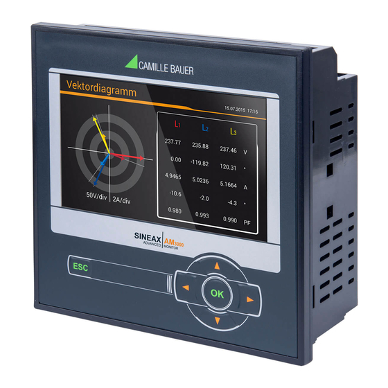
6.1 Parametrization of the device functionality A full parameterization of all functions of the device is possible directly at the device or via web browser. This assumes that user has the required access rights. For security reasons, the security features “Users and Permissions” (RBAC) and “Web security” (HTTPS) may be activated. - Page 38 b) Phasor verification: The phasor diagram shows a technical visualization of the current and voltage phasors, using a counter-clockwise rotation, independent of the real sense of rotation. The diagram is always built basing on the voltage of the reference channel (direction 3 o’clock) Correct installation (expectation) •...
-
Page 39: Ethernet Installation
6.4 Ethernet installation 6.4.1 Settings Before devices can be connected to an existing Ethernet network, you have to ensure that they will not disturb the normal network service. The rule is: None of the devices to connect is allowed to have the same IPv4/v6 address than another device already installed The device supports both IPv4 and IPv6 communication. - Page 40 Network settings of Standard interface Network settings of IEC61850 interface IPv4: Subnet mask For a direct communication between device and PC both devices need to be in the same network when the subnet mask is applied: Example 1 decimal binary 11000000 10101000 00000001 01100101 192.168.
- Page 41 IPv4: Mode >> DHCP If a DHCP server is available, alternatively the mode „DHCP“ or „DHCP, addresses only“ can be selected for the Standard interface. The device then gets all necessary information from the DHCP server. The difference between the two modes is that for “DHCP” also the DNS server address is obtained. The settings obtained from the DHCP server can be retrieved locally via the service menu.
-
Page 42: Connection Of The Standard Interface
6.4.2 Connection of the standard interface The standard RJ45 connector serves for direct connecting an Ethernet cable. Interface: RJ45 connector, Ethernet 100BaseTX Mode: 10/100 MBit/s, full / half duplex, Auto-negotiation Protocols: http, https, Modbus/TCP, NTP Functionality of the LED's AM1000 AM2000 / AM3000 •... -
Page 43: Mac Addresses
Functionality of the LED's AM1000 AM2000 / AM3000 State Meaning No network connection X1 green Existing network connection X2 green Flashing Active communication No error Red left No configuration, slow or no link BF (Bus failure) Flashing (2 Hz) No data exchange No error Red right Watchdog timeout, diagnosis active;... -
Page 44: Resetting The Communication Settings Of An Am1000 Without Display
6.4.6 Resetting the communication settings of an AM1000 without display If the communication settings of the Standard interface are no longer known, on devices with a display these settings may be locally displayed and modified. For devices without display this is not possible. The communication settings can then be reset to default settings via the reset button. -
Page 45: Profinet Io Interface
6.7 PROFINET IO interface The PROFINET interface provides a cyclical process image, which can be freely assembled by the user. 6.7.1 General stations description file (GSD) The GSD file describes the functionality available via the PROFINET interface of the device. During system design by means of a configuration tool (e.g. -
Page 46: Parameterization Of The Device
6.7.2 Parameterization of the device As soon as the GSD file has been imported, the device is available in the hardware catalog and can be integrated using drag&drop. There are three models available that represent the different designs of the whole device series. -
Page 47: Validity Of Measurements
Assembly of the cyclical process image In Slot 1 always the module ‘System state’ is present providing the following information: Meaning 0: Measurement system stopped or not reachable 1: Measurement system running 0 ↔ 1: When the measurement system is running, the bit changes its state when the value of at least one of the modules changes 2…31 not used, currently set to 0... -
Page 48: Profinet State
6.7.4 PROFINET state • For devices with display the present PROFINET state is shown in the status bar: Data exchange with IO controller inactive Data exchange with IO controller active • The PROFINET status is always visible in the status bar on the device website: Data exchange with IO controller inactive Data exchange with IO controller active •... -
Page 49: Simulation Of Analog / Digital Outputs
6.8 Simulation of analog / digital outputs To check if subsequent circuits will work properly with output values provided by the device, using the service menu Simulation all analog or digital / relay outputs may be simulated. This is done by either entering analog output values or selecting discrete states for the digital outputs / relays. -
Page 50: Rbac Management
6.9.1 RBAC management The access control system described below is available for devices with Ethernet interface only. For devices without Ethernet see: Simple password protection. Each access to device data via website, local display or external software applications can be comprehensively protected using the role-based access control (RBAC) system. - Page 51 Users: During password definition the requirements for a secure password are checked and the result is displayed. Each new user can be created based on the permission template of an already existing user, but all of these permissions may be changed later. When defining / changing passwords the following restrictions must be considered: - Password length 8 up to 32 characters - At least three different types of characters must be used (uppercase, lowercase, numbers,...
- Page 52 When the application wants to communicate via REST interface with the device, it has to provide the API key and the session token via the cookie field in the request header, e.g.: Further information is provided in the document “http interface SINEAX PQx000” Assignment of user rights The assignment of the user rights granted for operation is done via the menu Settings | Security system | Users and permissions:...
-
Page 53: User Log In / Out Via Website
6.9.2 User log in / out via website a) If “anonymous” has no granted permissions Via website Remarks 1) Enter user name and password 2) Press <ENTER> or select “Login” If successful, depending on the permissions of the user logged in, the appropriate website is displayed b) If “anonymous”... -
Page 54: User Log In / Out Via Local Display
6.9.3 User log in / out via local display a) If “localgui” has no granted permissions Locally Remarks No information is displayed on the screen. Press <ESC> to enter the login screen. 1) Press <OK> to enter the user name 2) Proceed to password using 3) Press <OK>... -
Page 55: Simple Password Protection
6.9.4 Simple password protection For devices without Ethernet interface the RBAC is reduced to a simple password protection based on the standard user ‚admin‘. If the user and permissions management is activated, the user has to enter a password before executing protected functions. Protected functions are changing settings parameters or deleting or resetting measurement data via the service menu. -
Page 56: Whitelisting Clients
Before HTTPS communication can be used a root certificate needs to be installed. The user can either use a Camille Bauer certificate (default setting) or its own customer certificate. This may be changed when defining the Settings of the Security system. -
Page 57: Audit Log (Syslog)
The imported certificate is valid for all devices of the PQ, AM, DM and CU series. Agree to install the certificate if the below security warning appears: Customer certificate You may also use a customer server certificate with a private key, but for that you first need to change the Settings of the Security system in the item Web Security. - Page 58 Example of a security log: The severity of each message is shown in a color code, which may also serve as filter criteria. Each entry into this list may, if activated, also be transferred to a central log-server using the SYSLOG protocol for security auditing.
-
Page 59: Operating The Device
7. Operating the device 7.1 Operating elements Operation is performed by means of 6 keys: 4 keys for navigation ( , , , ) and for the selection of values OK for selection or confirmation ESC for menu display, terminate or AM1000... -
Page 60: Measurement Displays And Used Symbols
7.3 Measurement displays and used symbols For displaying measurement information the device uses both numerical and numerical-graphical measurement displays. Examples Measurement information 2 measured quantities (AM2000/AM3000) 4 measured quantities (AM2000/AM3000) 2x4 measured quantities (AM2000/AM3000) 2x4 measured quantities with min/max (AM2000/AM3000) 4 measured quantities (AM1000) Graphical measurement display (AM1000) Further examples... - Page 61 Incoming / outgoing / inductive / capacitive The device provides information for all four quadrants. Quadrants are normally identified using the roman numbers I, II, III and IV, as shown in the adjacent graphic. Depending on whether the system is viewed from the producer or consumer side, the interpretation of the quadrants is changing: The energy built from the active power in the quadrants I+IV can either been seen as delivered or consumed active energy.
-
Page 62: Resetting Measurement Data
7.4 Resetting measurement data • Minimum and maximum may be reset during operation. The reset may be performed in groups using the service menu. Group Values to be reset Min/max values of voltages, currents and frequency Min/max values of Power quantities (P,Q,Q(H1),D,S); min. load factors Min/max values of power mean-values, bimetal slave pointers and free selectable mean-values Maximum values of harmonic analysis: THD U/I, TDD I, individual harmonics U/I All imbalance maximum values of voltage and current... - Page 63 • Limit values: Selection of up to 12 quantities to monitor, limit values for ON/OFF, event text • Digital inputs: Debounce time (minimum pulse width), pulse rate and polarity of the digital inputs • Fault current: Configuration of the fault current channels, especially alarm and pre-warning limits, transformer ratios as well as response and dropout delay •...
-
Page 64: Configuration Via Web Browser
7.5.2 Configuration via web browser It’s recommended to use either Google-Chrome or Firefox as browser. Internet Explorer works with limitations only (partly missing texts, firmware update not possible) For configuring via Webbrowser you have to display the device website using: •... - Page 65 Possibly modifications need to be saved in the device, before all parameters have been set. In such a case the following message appears: If this request is not confirmed unsaved modifications of the present device configuration may get lost. Loading / saving configuration files The user can save the present device configuration on a storage media and reload it from there.
-
Page 66: Alarming
7.6 Alarming The alarming concept is very flexible. Depending on the user requirements simple or more advanced monitoring tasks may be realized. The most important objects are limit values on base quantities, the monitoring of fault-current, monitoring functions and the summary alarm. 7.6.1 Limit values on base quantities Using limit values either the exceeding of a given value (upper limit) or the fall below a given value... -
Page 67: Monitoring Fault-Currents
7.6.2 Monitoring fault-currents Each (optional) fault current module provides two channels for monitoring residual or fault current. For each of the channels an alarm and a pre-warning limit can be defined, which can be used as follows: … Activating a summary alarm when the alarm limit is violated or a breakage occurs (2mA input only) …... -
Page 68: Temperature Monitoring
7.6.3 Temperature monitoring Each (optional) temperature module provides two channels for temperature monitoring. Used for Pt100 measurement • Up to 2 limit values • Short circuit and wire / sensor breakage monitoring Used for PTC monitoring • Monitoring the PTC response temperature •... -
Page 69: Monitoring Functions
7.6.4 Monitoring functions By means of monitoring functions the user can define an extended condition monitoring, e.g. for triggering an over-current alarm, if one of the phase currents exceeds a certain limit value. The states of all monitoring functions …will be shown in the alarm list (“Events” via main menu) …build a summary alarm state Logic inputs Up to three states of limit values, fault-current or temperature monitoring, logic inputs or other monitoring... -
Page 70: Summary Alarm
7.6.5 Summary alarm The summary alarm combines the states of all monitoring function MFx to a superior alarm-state of the overall unit. For each monitoring function you may select if it is used for building the summary alarm state. If at least one of the used functions is in the alarm state, the summary alarm is also in the alarm state. If an optional failure-current monitoring is present, the detection of an alarm state or a breakage of the measurement line (2mA inputs only) activates directly the summary alarm. -
Page 71: Data Recording
7.7 Data recording The optional data logger provides long-term recordings of measurement progressions and events. In addition, file based information can periodically created using the data export scheduler. Such data can be stored internally and / or securely sent to a SFTP server. The recording is performed in endless mode (oldest data will be deleted, as soon as the associated memory is used for more than 80%). - Page 72 Displaying the chronology of the mean values The chronology of the mean values is available via the menu Energy and is divided in two groups: • Pre-defined power mean values • User-defined mean values Selection of the mean values group The selection of the mean-value quantity to display can be performed via choosing the corresponding register.
- Page 73 Weekly display Weekly display: Reading Mean values in table format Displaying the chronology of meter contents The chronology of meters is available via the menu Energy and is divided in two groups: • Pre-defined meters • User-defined meters From the difference of two successive meter readings the energy consumption for the dedicated time range can be determined.
-
Page 74: User-Defined Events
Meter content readings in table form Displaying data locally The selection works in principle in the same way as with the WEB-GUI. There are the following differences: • The individual measured quantities are arranged in a display matrix and can be selected via navigation. •... - Page 75 Example of an event list Displaying data locally The selection works in principle in the same way as with the WEB-GUI. There is the following difference: • The number of displayable events is limited to 25 PM 1000162 000 14 Device handbook SINEAX AMx000 75/118...
-
Page 76: Disturbance Recorder (Am1000 / Am3000 Only)
7.7.3 Disturbance recorder (AM1000 / AM3000 only) Configuration of the events to record The device monitors the events voltage dip, swell and interruption. The user can define the threshold levels for these events in the menu Settings | Disturbance Logger. Display of disturbance recordings (locally) Recorded disturbances are available in the form of a logbook. - Page 77 Display matrix on the local display (AM1000) Restriction of the quantities to display on the local display The user can adapt the displayed information to its needs. Once the graphic is displayed, the setting window for the selection of the quantities to display is entered by pressing <OK>. Voltage display Current display Mixed display...
- Page 78 Display of disturbance recordings (WEB-GUI) As with the local GUI, recorded disturbances are available in the form of a logbook. By selecting a list entry the graphical display of the measured values during this event is entered. By selecting a time range via left mouse key, the graphical event display may be zoomed.
-
Page 79: Micro Sd Card (Am2000/3000 Only)
7.7.4 Micro SD card (AM2000/3000 only) Devices with data logger are supplied with a micro SD-Card, which provides long recording times. Activity The red LED located next to the SD card signals the logger activity. When data is written to the SD card the LED becomes shortly dark. -
Page 80: Measurement Information In File Format
7.8 Measurement information in file format Using the data export scheduler, measurement information may be provided also in file format. Such files can then: • periodically being sent to an SFTP server • locally stored in the device and downloaded via webpage 7.8.1 Creating periodic file data A periodic generation of CSV files can be setup using the Data export scheduler via the menu Settings | Data export. -
Page 81: Accessing File Information Via Webpage
CSV settings CSV files are intended for transmitting statistics of mean values. You may adjust the below parameters to adapt the file format and the content of the created files to your requirements. • The Separator separates the individual entries on a text line for later display in table form. •... -
Page 82: Periodical Sending To A Sftp Server
7.8.3 Periodical sending to a SFTP Server If in the data export scheduler the sending to an SFTP server was selected as action, the appropriate files will be sent periodically to the SFTP server defined in the settings of the communication. For improving security you may select that the device connects to trusted hosts only. -
Page 83: Service, Maintenance And Disposal
8. Service, maintenance and disposal 8.1 Calibration and new adjustment Each device is adjusted and checked before delivery. The condition as supplied to the customer is measured and stored in electronic form. The uncertainty of measurement devices may be altered during normal operation if, for example, the specified ambient conditions are not met. -
Page 84: Technical Data
9. Technical data Inputs Nominal current: adjustable 1...5 A; max. 7.5 A (sinusoidal) Measurement category: 300V CAT III Consumption: ≤ I x 0.01 Ω per phase Overload capacity: 10 A continuous 100 A, 5 x 1 s, interval 300 s Nominal voltage: 57.7…400 V (UL: 347V... - Page 85 Zero suppression, range limitations The measurement of specific quantities is related to a pre-condition which must be fulfilled, that the corresponding value can be determined and sent via interface or displayed. If this condition is not fulfilled, a default value is used for the measurement. Quantity Condition Default...
- Page 86 Relays via plug-in terminals Contact: changeover contact Load capacity: 250 V AC, 2 A, 500 VA 30 V DC, 2 A, 60 W Passive digital inputs via plug-in terminals Nominal voltage 12 / 24 V DC (30 V max.) Input current <...
- Page 87 Temperature inputs via plug-in terminals Number of channels: Measurement current: <1.0mA Connection: 2-wire Input protection: Voltage limitation via protective diode Used for Pt100 measurement Measurement range: -50 up to 250°C / -58 up to 482°F Uncertainty: ±1.0 % of measurement ±1 K Connection monitoring: Short-circuit (<20 Ω), wire / sensor breakage (>1000 Ω) Alarm limits:...
- Page 88 Uninterruptible power supply (UPS) Type: VARTA Easy Pack EZPAckL, UL listed MH16707 Nominal voltage: 3.7V Capacity: 1150 mAh min., 4.5 Wh Operating duration: 5 times 3 minutes Life time: 3 up to 5 years, depending on operating and ambient conditions Ambient conditions, general information Operating temperature: •...
- Page 89 Safety The current inputs are galvanically isolated from each other Protection class: II (protective insulation, voltage inputs via protective impedance) Pollution degree: Protection: Front: IP40, IP54 (with sealing joint); Housing: IP30; Terminals: IP20 IP54 remark Sealing joint must be applied on the entire circumference of the housing;...
- Page 90 Applied regulations, standards and directives IEC/EN 61 010-1 Safety regulations for electrical measuring, control and laboratory equipment IEC/EN 61000-4-30 Ed.3 Power quality measurement methods IEC/EN 61000-4-7 General guide on harmonics and interharmonics measurements EN 50160 Voltage characteristics of electricity supplied by public distribution systems IEC/EN 60688 Electrical measuring transducers for converting AC electrical variables into analog or digital signals...
-
Page 91: Dimensional Drawings
10. Dimensional drawings AM2000 / AM3000: All dimensions in [mm] AM1000 with display: All dimensions in [mm] PM 1000162 000 14 Device handbook SINEAX AMx000 91/118... - Page 92 AM1000 for hat-rail with display: All dimensions in [mm] AM1000 for hat-rail without display: All dimensions in [mm] PM 1000162 000 14 Device handbook SINEAX AMx000 92/118...
-
Page 93: Annex
Annex A Description of measured quantities Used abbreviations Single phase system Split phase; system with 2 phases and center tap 3-wire system with balanced load 3Lb.P 3-wire system with balanced load, phase shift (only 2 voltages connected) 3-wire system with unbalanced load 3Lu.A 3-wire system with unbalanced load, Aron connection (only 2 currents connected) 4-wire system with balanced load... - Page 94 Measurement ● ● √ √ √ √ √ √ √ √ √ Apparent power S ● ● √ √ √ Apparent power S1 Apparent power S2 ● ● √ √ √ Apparent power S3 ● ● √ √ Fundamental apparent power S(H1) ●...
- Page 95 Reactive power Most of the loads consume a combination of ohmic and inductive current from the power system. Reactive power arises by means of the inductive load. But the number of non-linear loads, such as RPM regulated drives, rectifiers, thyristor controlled systems or fluorescent lamps, is increasing. They cause non- sinusoidal AC currents, which may be represented as a sum of harmonics.
- Page 96 Zero displacement voltage U Starting from the generating system with star point E (which is normally earthed), the star point (N) on load side is shifted in case of unbalanced load. The zero displacement voltage between E und N may be determined by a vectorial addition of the voltage vectors of the three phases: = - (U...
-
Page 97: A2 Harmonic Analysis
A2 Harmonic analysis The harmonic analysis is performed according IEC 61000-4-7 over 10 cycles at 50Hz or 12 cycles at 60Hz. If a measured quantity is available depends on the selected system. Measurement ● ● √ √ √ √ √ √... -
Page 98: A3 System Imbalance
A3 System imbalance Measured quantity UR1: Positive sequence [V] ● √ √ √ √ UR2: Negative sequence [V] ● √ √ √ √ U0: Zero sequence [V] ● √ U: Imbalance UR2/UR1 ● ● √ √ √ √ U: Imbalance U0/UR1 ●... -
Page 99: A4 Mean Values And Trend
A4 Mean values and trend Measured quantity Active power I+IV 10s...60min. ● ● ● ● Active power II+III 10s...60min. ● ● ● ● Reactive power I+II 10s...60min. ● ● ● ● Reactive power III+IV 10s...60min. ● ● ● ● Apparent power 10s...60min. -
Page 100: A5 Meters
A5 Meters Measured quantity Active energy I+IV, high tariff ● ● ● ● ● ● ● ● ● ● ● ● ● ● ● ● ● ● Active energy II+III, high tariff ● ● ● ● ● ● ● ● ●... -
Page 101: B Display Matrices
B Display matrices B0 Used abbreviations for the measurements Instantaneous values Name Measurement identification Unit Description Voltage system TRMS Voltage between phase L1 and neutral TRMS Voltage between phase L2 and neutral TRMS Voltage between phase L3 and neutral TRMS Voltage between phases L1 and L2 TRMS Voltage between phases L2 and L3... - Page 102 Minimum and maximum of instantaneous values Name Measurement identification Unit Description U_MM Minimum and maximum value of U TRMS U1N_MM Minimum and maximum value of U1N TRMS U2N_MM Minimum and maximum value of U2N TRMS U3N_MM Minimum and maximum value of U3N TRMS U12_MM Minimum and maximum value of U12...
- Page 103 Mean-values, trend and bimetal current Name Measurement identification Unit Description (t2) (mu) Mean-value 1 (t2) (mu) Mean-value 2 …. (t2) (mu) …. (t2) (mu) Mean-value 11 (t2) (mu) Mean-value 12 TR_M1 Trend mean-value 1 (t2) (mu) TR_M2 (t2) (mu) Trend mean-value 2 ….
- Page 104 Graphical measurement displays Name Presentation Description Graphic of the power triangle consisting of: • Active, reactive and apparent power Px, Qx, Sx • Distortion reactive power Dx Px_TRIANGLE • Fundamental reactive power Qx(H1) • cos(φ) of fundamental • Active power factor PFx PF_MIN Graphic: Minimum active power factor PF in all 4 quadrants Cφ_MIN...
- Page 105 Graphic: Odd harmonics 3 up to 49 + Total Harmonic HO_IX Distortion of all currents Graphic: Odd harmonics 3 up to 49 + Total Harmonic HO_UX (as HO_IX) Distortion of all voltages Graphic: Even harmonics 2 up to 50 + Total Harmonic HE_IX (as HO_IX) Distortion of all currents...
-
Page 106: B1 Display Matrices For Single Phase System
B1 Display matrices for single phase system Device Corresponding matrix AM1000 U_MM I_MAX P_MAX F_MM P_MAX Q_MAX S_MAX P_TRIANGLE PF_MIN Cφ_MIN I> 1.1 / 1.2 ϑ 1.1 / 1.2 AM2000 U_MM I_MAX P_MAX F_MM P_MAX Q_MAX S_MAX P_TRIANGLE PF_MIN Cφ_MIN I>... -
Page 107: B2 Display Matrices For Split-Phase (Two-Phase) Systems
B2 Display matrices for split-phase (two-phase) systems Device Corresponding matrix AM1000 U1N_MM U2N_MM U_MM F_MM I1_MAX I2_MAX P_MAX P1_MAX Q_MAX P2_MAX S_MAX Q1_MAX Q2_MAX P_TRIANGLE P1_TRIANGLE P2_TRIANGLE PF_MIN Cφ_MIN I> 1.1 / 1.2 ϑ 1.1 / 1.2 AM2000 U1N_MM U2N_MM U_MM F_MM I1_MAX... -
Page 108: B3 Display Matrices For 3-Wire System, Balanced Load
B3 Display matrices for 3-wire system, balanced load Device Corresponding matrix AM1000 U12_MM U23_MM U31_MM UR2R1 F_MM UR21_MAX I_MAX P_MAX Q_MAX S_MAX P_TRIANGLE PF_MIN Cφ_MIN I> 1.1 / 1.2 ϑ 1.1 / 1.2 AM2000 U12_MM U23_MM U31_MM UR2R1 F_MM UR21_MAX I_MAX P_MAX Q_MAX... -
Page 109: B4 Display Matrices For 3-Wire System, Balanced Load, Phase Shift
B4 Display matrices for 3-wire system, balanced load, phase shift Device Corresponding matrix AM1000 U_MM I_MAX P_MAX F_MM P_MAX Q_MAX S_MAX P_TRIANGLE PF_MIN Cφ_MIN I> 1.1 / 1.2 ϑ 1.1 / 1.2 AM2000 U_MM I_MAX P_MAX F_MM P_MAX Q_MAX S_MAX P_TRIANGLE PF_MIN Cφ_MIN... -
Page 110: B5 Display Matrices For 3-Wire Systems, Unbalanced Load
B5 Display matrices for 3-wire systems, unbalanced load Device Corresponding matrix AM1000 U12_MM U23_MM U31_MM UR2R1 F_MM UR21_MAX I1_MAX I2_MAX I3_MAX IR2R1 IR21_MAX P_MAX Q_MAX S_MAX P_TRIANGLE PF_MIN Cφ_MIN I> 1.1 / 1.2 ϑ 1.1 / 1.2 AM2000 U12_MM U23_MM U31_MM UR2R1 F_MM... -
Page 111: B6 Display Matrices For 3-Wire Systems, Unbalanced Load, Aron
B6 Display matrices for 3-wire systems, unbalanced load, Aron Device Corresponding matrix AM1000 U12_MM U23_MM U31_MM UR2R1 F_MM UR21_MAX I1_MAX I2_MAX I3_MAX P_MAX Q_MAX S_MAX P_TRIANGLE PF_MIN Cφ_MIN I> 1.1 / 1.2 ϑ 1.1 / 1.2 AM2000 U12_MM U23_MM U31_MM UR2R1 F_MM UR21_MAX... -
Page 112: B7 Display Matrices For 4-Wire System, Balanced Load
B7 Display matrices for 4-wire system, balanced load Device Corresponding matrix AM1000 U_MM UNE_MAX I_MAX F_MM P_MAX Q_MAX S_MAX P_TRIANGLE PF_MIN Cφ_MIN I> 1.1 / 1.2 ϑ 1.1 / 1.2 AM2000 U_MM I_MAX P_MAX F_MM P_MAX Q_MAX S_MAX P_TRIANGLE PF_MIN Cφ_MIN I>... -
Page 113: B8 Display Matrices For 4-Wire Systems, Unbalanced Load
B8 Display matrices for 4-wire systems, unbalanced load Device Corresponding matrix AM1000 U1N_MM U12_MM U2N_MM U23_MM U3N_MM U31_MM F_MM UR21_MAX UNB_UR2_UR1 I1_MAX I2_MAX I3_MAX IN_MAX UNB_IR2_IR1 P1_MAX Q1_MAX S1_MAX P2_MAX Q2_MAX S2_MAX P3_MAX Q3_MAX S3_MAX P_MAX Q_MAX S_MAX P_TRIANGLE P1_TRIANGLE P2_TRIANGLE P3_TRIANGLE PF_MIN... -
Page 114: B9 Display Matrices For 4-Wire System, Unbalanced Load, Open-Y
B9 Display matrices for 4-wire system, unbalanced load, Open-Y Device Corresponding matrix AM1000 U1N_MM U12_MM U2N_MM U23_MM U3N_MM U31_MM F_MM UR21_MAX I1_MAX I2_MAX I3_MAX IN_MAX UNB_IR2_IR1 P1_MAX Q1_MAX S1_MAX P2_MAX Q2_MAX S2_MAX P3_MAX Q3_MAX S3_MAX P_MAX Q_MAX S_MAX P_TRIANGLE P1_TRIANGLE P2_TRIANGLE P3_TRIANGLE PF_MIN... -
Page 115: B10 Common Display Matrices
B10 Common display matrices Anzeigemenü Zugehörige Matrix ΣP_I_IV_HT ΣP_I_IV_NT ΣP_II_III _NT ΣP_II_III_HT ΣQ_I_II_HT ΣQ_I_II _NT ΣQ_III_IV _HT ΣQ_I_II _NT ΣMETER1 ΣMETER2 ΣMETER3 ΣMETER4 ΣMETER5 ΣMETER6 ΣMETER7 ΣMETER8 ΣMETER9 ΣMETER10 ΣMETER11 ΣMETER12 MT_P_I_IV MT_P_II_III MT_Q_I_II MT_Q_III_IV MT_S M1 / TR_M1 M1_MM M2 / TR_M2 M2_MM M3 / TR_M3... -
Page 116: C Logic Functions
C Logic functions The principal function of the logical gates is given in the following table, for simplicity shown for gates with two inputs only. older symbols function symbol truth table plain text ANSI 91-1984 DIN 40700 (alt) Function is true if all input conditions are fulfilled Function is true if at least one of the input... -
Page 117: Dfcc Statement
Camille Bauer AG. The correction of interference caused by such unauthorized modification, substitution or attachment will be the responsibility of the user. -
Page 118: Index
INDEX Basic measurements ..........93 Bimetal current ............99 Alarming ............... 66 earth fault monitoring ..........96 harmonic analysis ............ 97 Load factors ............. 95 Commissioning ............. 36 mean values and trend ..........99 Configuration meters ..............100 menu ................ 62 system imbalance ............
Need help?
Do you have a question about the SINEAX AM2000 and is the answer not in the manual?
Questions and answers