Table of Contents
Advertisement
Device handbook
A
-LED
PLUS
Operating Instructions A
with LED display or without display
PLUS
157 679-19
04/2016
(PM 1000357 000 01)
Camille Bauer Metrawatt AG
Aargauerstrasse 7
CH-5610 Wohlen / Switzerland
Phone: +41 56 618 21 11
Telefax: +41 56 618 35 35
e-Mail: info@cbmag.com
http://www.camillebauer.com
Advertisement
Table of Contents

Related Manuals for Camille Bauer APLUS-LED

Summary of Contents for Camille Bauer APLUS-LED
- Page 1 Operating Instructions A with LED display or without display PLUS 157 679-19 04/2016 (PM 1000357 000 01) Camille Bauer Metrawatt AG Aargauerstrasse 7 CH-5610 Wohlen / Switzerland Phone: +41 56 618 21 11 Telefax: +41 56 618 35 35 e-Mail: info@cbmag.com...
- Page 2 Legal information Warning notices In this document warning notices are used, which you have to observe to ensure personal safety and to prevent damage to property. Depending on the degree of danger the following symbols are used: If the warning notice is not followed death or severe personal injury will result.
-
Page 3: Table Of Contents
Contents 1. Introduction ........................5 1.1 Purpose of this document ......................5 1.2 Scope of supply ........................5 1.3 Further documents ........................5 2. Security notes ........................6 3. Device overview....................... 6 3.1 Brief description ........................6 3.2 Possible modes of operation ....................7 3.3 Monitoring and alarming ...................... - Page 4 7.6 Alarm handling ........................43 7.6.1 Alarm state display on the device ..................... 43 7.6.2 Display of alarm texts ........................43 7.6.3 Acknowledgment of alarms via display ..................... 44 7.7 Resetting of measurements ....................45 7.8 Configuration ........................46 7.8.1 Selection of the parameter to edit ..................... 50 7.8.2 Discrete selection ..........................
-
Page 5: Introduction
1. Introduction 1.1 Purpose of this document This document describes the universal measurement device for heavy-current quantities A . It is PLUS intended to be used by: • Installation personnel and commissioning engineers • Service and maintenance personnel • Planners Scope This handbook is valid for all hardware versions of the A with LED display or without display. -
Page 6: Security Notes
2. Security notes Device may only be disposed in a professional manner ! The installation and commissioning should only be carried out by trained personnel. Check the following points before commissioning: – that the maximum values for all the connections are not exceeded, see "Technical data" section, –... -
Page 7: Possible Modes Of Operation
3.2 Possible modes of operation The A can cover a wide range of possible input ranges without any hardware variance. The adaption PLUS to the input signal is performed by means of variable amplifying levels for current and voltage inputs. Depending on the application it makes sense to fix these levels by means of the configuration or to let them stay variable to achieve a maximum accuracy during measurement. -
Page 8: Monitoring And Alarming
3.3 Monitoring and alarming The logic module integrated in the A is a powerful feature to monitor critical situations without delay PLUS on device side. By implementing this local intelligence a safe monitoring can be realized which is independent of the readiness of the control system. 3.3.1 Alarming concept How alarms are handled is decided during the configuration of the device. - Page 9 Logic output determined from all involved logic inputs Corresponds to signal Z, delayed by the switch-in resp. dropout delay Output signal of the logic function State of the subsequent operation (e.g. of a relay), corresponds normally to A, but may be inverted (subsequent operation: relay OFF) Alarm reset inactive, switch-in and dropout delay 3s, follow-up action not inverted Acknowledgment of...
-
Page 10: Logic Components
3.3.2 Logic components The logic outputs are calculated via a two level logical combination of states, which are present at the inputs. Usable components are AND, OR and XOR gates as well as their inversions NAND, NOR and XNOR. The principal function of the logical gates is given in the following table, for simplicity shown for gates with two inputs only. -
Page 11: Limit Values
3.3.3 Limit values States of limit values are the most important input quantities of the logic module. Depending on the application, limits either monitor the exceeding of a given value (upper limit) or the fall below a given value (lower limit). Limits are defined by means of two parameters, the limit for the ON and the limit for the OFF state. -
Page 12: Sequence Of Evaluation
3.3.4 Sequence of evaluation The evaluation of the logic module is performed from top to bottom and from left to right: 1. Y1, Y2, Y3, Y4 2. Z1, Z2, Z3, Z4 3. D1, D2, D3, D4 4. A1, A2, A3, A4 ►... -
Page 13: Free Modbus Image
3.4 Free Modbus image Accessing measured data of a Modbus device often needs some special effort, if the interesting measurements are stored in different, non continuous register areas. This way multiple telegrams must be sent to the device to read all data. This needs time and it's very likely, that the measurements don't originate from the same measurement cycle. -
Page 14: Mechanical Mounting
4. Mechanical mounting ► The standard version of the A is designed for panel mounting as shown below PLUS ► The version without display with top-hat rail adapter may be clipped onto a top-hat rail according to EN50022 Please ensure that the operating temperature limits are not exceeded when determining the place of mounting (place of measurement): -10 ... -
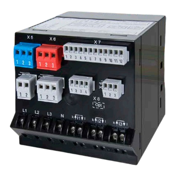
Page 15: Electrical Connections
5. Electrical connections Ensure under all circumstances that the leads are free of potential when connecting them ! 5.1 General safety notes Please observe that the data on the type plate must be adhered to ! The national provisions (e.g. in Germany VDE 0100 “Conditions concerning the erection of heavy current facilities with rated voltages below 1000 V”) have to be observed in the installation and material selection of electric lines! Nameplate of a... -
Page 16: Electrical Connections Of The I/Os
5.2 Electrical connections of the I/Os I/O no. Terminal I/O extension 1 I/O extension 2 PLUS 1, 2, 3 Relay 1, 2 Digital input 3, 4 Digital output 1, 2, 3 Relay Relay 1, 2, 3 Relay Relay 1, 2 Digital I/O Digital I/O 3, 4... -
Page 17: Inputs
5.4 Inputs All voltage measurement inputs must originate at circuit breakers or fuses rated 10 Amps or less. This does not apply to the neutral connector. You have to provide a method for manually removing power from the device, such as a clearly labeled circuit breaker or a fused disconnect switch. - Page 18 3L. b Three wire system, balanced load, current measurement via L1 Direct connection With current transformer PLUS PLUS With current and voltage transformer In case of current measurement via L2 or L3 connect voltages according to the following table: PLUS Current Terminals I1-k...
- Page 19 3L. U b Three wire system, unbalanced load Direct connection With current transformers PLUS PLUS With current and 3 single-pole isolated voltage transformers PLUS 3L. U A Three wire system, unbalanced load, Aron connection Direct connection With current transformers PLUS PLUS With current and 3 single-pole isolated voltage transformers...
- Page 20 4L. U b Four wire system, unbalanced load Direct connection With current transformers PLUS PLUS With current and 3 single-pole isolated voltage transformers PLUS 4L. U Y Four wire system, unbalanced load, Open-Y Direct connection With current transformers PLUS PLUS With current and 2 single-pole isolated voltage transformers PLUS...
-
Page 21: Rogowski Current Inputs
SP. P H Split-phase ("two phase system"), unbalanced load Direct connection With current transformers PLUS PLUS 5.5 Rogowski current inputs The connection of the Rogowski coils is performed depending on the selected system type, as shown in chapter 5.4 above. However, instead of current transformers a Rogowski coils is placed around each current-carrying conductor. -
Page 22: Power Supply
5.6 Power supply A marked and easily accessible current limiting switch has to be arranged in the vicinity of the device for turning off the power supply. Fusing should be 10 Amps or less and must be rated for the available voltage and fault current. 5.7 Relays When the device is switched off the relay contacts are de-energized, but dangerous voltages may be present. -
Page 23: Digital Inputs And Outputs
5.8 Digital inputs and outputs For the digital inputs / outputs an external power supply of 12 / 24V DC is required. The power supply shall not exceed 30V DC ! The plug-in terminal X7 is available for device versions with I/O extension PCB only. - Page 24 Usage as digital output ► Alarm output for logic module ► State reporting ► Pulse output to an external counter (acc. EN62053-31) ► Remote controllable state output via bus interface Driving a relay Technical data Rated current 50 mA (60 mA max.) Switching frequency (S0) ≤...
-
Page 25: Analog Outputs
5.9 Analog outputs Analog outputs are available for devices with I/O extension 1 only. See nameplate. Connection to an analog input card of a PLC or a control system The A is an isolated measurement device. In PLUS addition the particular outputs are galvanically isolated. -
Page 26: Profibus Dp Interface
5.11 Profibus DP interface The 9-pin DSUB socket serves the connection of a standard Profibus plug. In a bus terminal device, the bus line must be terminated with resistors in the bus plug. Then standard pin assignment is as follows: Name Description RxD/TxD-P... -
Page 27: Commissioning
6. Commissioning Before commissioning you have to check if the connection data of the transducer match the data of the plant (see nameplate). If so, you can start to put the device into operation by switching on the power supply and the measurement inputs. -
Page 28: Parametrization Of The Device Functionality
6.2 Parametrization of the device functionality Operating the software The device configuration is divided into registers, which contain thematically the different function blocks of the device, e.g. "input", "limit values", "display". Thereby of course there are interdependencies, which have to be considered. If e.g. a current limit value is defined and subsequently the ratio of the current transformer is changed, there is a high probability that the limit value is changed as well. -
Page 29: Installation Check
ONLINE / OFFLINE The parametrization may be performed ONLINE (with existing connection to the device) or OFFLINE (without connection to the device). To perform an ONLINE configuration first the configuration of the connected device, and therewith its hardware version, is read. A modified configuration can then be downloaded to the device and stored on the hard disk of the computer for archiving. -
Page 30: Installation Of Ethernet Devices
Installation of Ethernet devices 6.4.1 Connection Before devices can be connected to an existing Ethernet network, you have to ensure that they will not disturb the normal network service. The rule is: None of the devices to connect is allowed to have the same IP address than another device already installed The factory setting of the IP address of A is: 192.168.1.101... -
Page 31: Network Installation Using The Cb-Manager Software
This can be done very easily, using the CB-Manager software to search for devices which have a MAC address 00-12-34-AE-xx-xx, which identifies the device as A of Camille Bauer. Because PLUS this is performed by means of a UDP broadcast telegram, the devices are allowed to have the same network address at the beginning, e.g. -
Page 32: Network Installation By Means Of Local Programming
Example Initial situation Installed system 192.168.1.101 192.168.1.101 192.168.1.101 192.168.57.230 192.168.57.231 192.168.57.232 00-12-34-AE-00-01 00-12-34-AE-00-04 00-12-34-AE-00-07 00-12-34-AE-00-01 00-12-34-AE-00-04 00-12-34-AE-00-07 Devices outside the local network Devices which are not in the same network as the PC (e.g. in the Internet) can not be found and have to be added manually to the device list by means of . -
Page 33: Time Synchronization Via Ntp-Protocol
6.4.4 Time synchronization via NTP-protocol For the time synchronization via Ethernet NTP (Network Time Protocol) is the standard. Corresponding time servers are used in computer networks, but are also available for free via Internet. Using NTP it's possible to hold all devices on a common time base. Two different NTP servers may be defined. -
Page 34: Installation Of Profibus Dp Devices
6.5 Installation of Profibus DP devices The Profibus DP interface allows data exchange with a control system via Profibus-DP V0. The modular device model provides maximum protocol efficiency. Required measured variables are determined during engineering and arranged as a fixed process image. The control system does not require any intelligence for the evaluation of the data (no tunneling protocol). -
Page 35: Protection Against Device Data Changing
6.6 Protection against device data changing Data stored in the device may be modified or reset via communication interface or via the keys on the device itself. To restrict these possibilities on-site, via CB-Manager the security system in the device can be activated (factory default: not activated). -
Page 36: Operating The Device
7. Operating the device 7.1 Display and operating elements 2 u d 3 Phase reference of measurement, sign of measurement, minimum or maximum value, e.g. U (maximum value) 230. 4 4-digit display of measurements. On each change of the measurement display the short form of the quantities to display is shown first. -
Page 37: Operating Modes
7.2 Operating modes The device supports, along with the configuration mode, three different operating modes. Normally the device is in the measurement display mode, but may be temporarily switched for the reading of the meters or for the display of alarm texts. Measurement display : Is the normal operating mode of the device. -
Page 38: Setting The Display Brightness
7.3 Setting the display brightness The brightness of the display can be set to one of thirteen levels. Brighter: Press key longer than 2s; brightness will increase in steps Darker: Press key longer than 2s; brightness will decrease in steps 38/89 Device handbook A with / without LED display, 157 679-19, 04/2016... -
Page 39: Display Modes
7.4 Display modes The device supports four different display modes. They differ in the way measurement data is presented and which measurement data is provided. ► The selection of the display mode is described under Configuration FULL mode The measurement images of all displayable data are arranged in a matrix form. The selection is performed by means of the arrow keys: One image to the left. - Page 40 REDUCED mode This display mode is a reduced version of the FULL mode. Some of the images or complete lines, e.g. the grayed data in the below example, can be hidden. So the display may be adapted easily to the information requirements on-site.
- Page 41 USER mode This display mode allows a free assembly of up to 20 measurement images. Also the fourth line may be different for each image. Any meter value or another quantity (Ux, Ix, Px, Qx, Sx) may be assigned. The images are arranged among each other and selectable via the keys Image of the next line is displayed.
-
Page 42: Meter Reading
7.5 Meter reading A reading of the meter contents may be performed at any time, independent of the present selected display mode. When a meter content is displayed it may be reset to zero if the necessary rights have been granted during the configuration of the device. -
Page 43: Alarm Handling
7.6 Alarm handling How alarms are handled is fixed during the configuration of the device. A detailed description about the alarming concept is here: ► Monitoring und alarming 7.6.1 Alarm state display on the device The yellow state LED's are intended for alarming and alarm state display on-site. The displayed states are the result of the state information analysis, defined by the user in the logic module. -
Page 44: Acknowledgment Of Alarms Via Display
7.6.3 Acknowledgment of alarms via display Acknowledgment is not required if "acknowledgement of alarm LEDs required" in the logic module configuration is not selected. The acknowledgment of alarms may be performed via the keys on the device. To do so, the alarm to acknowledge must be actually displayed. -
Page 45: Resetting Of Measurements
7.7 Resetting of measurements The A provides minimum and maximum values of different measured quantities as well as energy PLUS meters and operating hour counters. All of them may be reset during operation. Basic principle RESET: Press key (longer than 2s) while the quantity to reset is displayed Example: Reset of U1N and U1N U 1 N... -
Page 46: Configuration
7.8 Configuration A complete configuration of the A is possible via CB-Manager software only using the configuration PLUS interface of the device. On device side only the parameters described below may be modified. To do so, a configuration menu is provided. Starting the configuration menu: Press (longer than 2s);... - Page 47 Communication interface c._ _ _ The possible settings depend on the device version selected. The following combinations may be available: Bus connection Menu 1 Menu 2 c. 4 85 RS-485 (Modbus/RTU protocol) c. E th Ethernet (Modbus/TCP protocol) c. 4 85 c.
- Page 48 ►Ethernet (Modbus/TCP-interface) Menu Range of values Description z.B. 192.168.057.011 IP address: Must be unique for each device ! SUb. n z.B. 255.255.255.000 Subnet mask GAtE z.B. 192.168.057.001 Gateway address PoRT 1...65535 The TCP port for the Modbus/TCP communication, usually this is port 502. ►Profibus DP Menu Range of values...
- Page 49 Further menu parameters Menu Range of values Description MOdE Display mode of the device. USER and LOOP mode can FULL, redU, User, LOOP be activated only, if at least one free measurement image DISPLAY MODE Display modes has been defined ! rAte 100...5000 Refresh rate of the display.
-
Page 50: Selection Of The Parameter To Edit
Setting time and date All time information stored in the device is referenced to UTC (Universal Time Coordinated). For a better understanding the time/date information displayed on the display can be converted to local time by defining a time zone offset. This offset is added to the internal UTC time before the time information is displayed. -
Page 51: Discrete Selection
7.8.2 Discrete selection The configuration of parameters, which can accept a limited number of values only, is implemented by means of selecting a value from a list. In the example shown below to modify the display mode normally the discrete values FULL, REDU, USER and LOOP are available. REDU USER Example: Change MODE (... -
Page 52: Data Logger
7.9 Data logger The data logger offers a periodical acquisition of measurement data, such as recording load profiles, measurement fluctuations or meter readings as well as event triggered recordings of alarm states or distubances. This storage medium used is an SD card, which allows almost unlimited recordings and an easy exchanging on-site. -
Page 53: Access To Logger Data
7.9.3 Access to logger data Only for device versions with Ethernet a direct access tot he logger data via interface is possible. For all other versions you have to remove the SD card first and to access the recorded data using an internal or external card reader. -
Page 54: Service, Maintenance And Disposal
8. Service, maintenance and disposal 8.1 Protection of data integrity The A supports security mechanism, which serve to prevent manipulation or undesired modifications PLUS of device data. ► Protection against device data modifications 8.2 Calibration and new adjustment Each device is adjusted and checked before delivery. The condition as supplied to the customer is measured and stored in electronic form. -
Page 55: Technical Data
9. Technical data Inputs Nominal current: adjustable 1...5 A Current measurement via Rogowski coils Maximum: 7.5 A (sinusoidal) Range: 0…3000A, auto-ranging ≤ I x 0.01 Ω per phase Consumption: See operating instructions of Rogowski coil Overload capacity: 10 A continuous ACF3000 for further information 100 A, 10 x 1 s, interval 100 s Nominal voltage:... - Page 56 Zero suppression, range limitations The measurement of specific quantities is related to a pre-condition which must be fulfilled, that the corresponding value can be determined and sent via interface or displayed. If this condition is not fulfilled, a default value is used for the measurement. Quantity Condition Default...
- Page 57 I/O interface Available inputs and outputs Basic unit - 1 relay output, changeover contact - 1 digital output (fixed) - 1 digital input (fixed) I/O extension 1 - 2 relay outputs, changeover contact - 4 bipolar analog outputs - 2 digital inputs/outputs, each configurable as input or output I/O extension 2 - 2 relay outputs, changeover contact - 6 digital inputs/outputs, each configurable as input or output...
- Page 58 Interfaces Modbus/RTU X4 / X8 via plug-in terminals Protocol: Modbus RTU Physics: RS-485, max. 1200m (4000 ft) Baud rate: 2'400, 4'800, 9'600, 19'200, 38'400, 57'600, 115'200 Baud ≤ 32 Number of participants: Profibus X8 via 9-pin D-sub socket Protocol: Profibus DP Physics: RS-485, 100…1200m (depending on baud rate and cable type used) Baud rate:...
- Page 59 Security The current inputs are galvanically isolated from each other Protection class: II (protective insulation, voltage inputs via protective impedance) Pollution degree: Protection: IP64 (front), IP40 (housing), IP20 (terminals) Measurement category: CAT III, CATII (relays) Rated voltage power supply: 265 V AC (versus earth): Relays: 250 V AC I/O’s: 30 V DC...
-
Page 60: Dimensional Drawings
10. Dimensional drawings with display PLUS 60/89 Device handbook A with / without LED display, 157 679-19, 04/2016 PLUS... - Page 61 without display PLUS 61/89 Device handbook A with / without LED display, 157 679-19, 04/2016 PLUS...
-
Page 62: Annex
Annex A Description of measured quantities Used abbreviations Single phase system Split phase; system with 2 phases and centre tap 3-wire system with balanced load 3-wire system with unbalanced load 3Lu.A 3-wire system with unbalanced load, Aron connection (only 2 currents connected) 4-wire system with balanced load 4-wire system with unbalanced load 4Lu.O... - Page 63 Measurement ● √ √ √ √ √ √ √ √ Power factor PF ● √ √ √ Power factor PF1 ● √ √ √ Power factor PF2 ● √ √ Power factor PF3 ● √ √ √ √ √ √ √...
- Page 64 Zero displacement voltage U Starting from the generating system with star point E (which is normally earthed), the star point (N) on load side is shifted in case of unbalanced load. The zero displacement voltage between E und N may be determined by a vectorial addition of the voltage vectors of the three phases: = - (U...
-
Page 65: A2 Harmonic Analysis
A2 Harmonic analysis Measurement ● ● √ √ √ √ √ THD Voltage U1N/U ● ● √ √ √ √ THD Voltage U2N ● ● √ √ THD Voltage U3N ● ● √ √ √ THD Voltage U12 ● ● √... -
Page 66: A3 System Imbalance
A3 System imbalance Measured quantity ● √ √ √ √ UR1: Positive sequence [V] ● √ √ √ √ UR2: Negative sequence [V] ● √ U0: Zero sequence [V] ● ● √ √ √ √ U: Imbalance UR2/UR1 ● ● √... -
Page 67: A4 Reactive Power
A4 Reactive power Measured quantity ● ● √ √ √ √ √ √ √ √ Distortion reactive power D ● ● √ √ √ Distortion reactive power D1 ● ● √ √ √ Distortion reactive power D2 ● ● √ √... - Page 68 The reactive power may be divided in a fundamental and a distortion component. Only the fundamental reactive power may be compensated directly by means of the classical capacitive method. The distortion components have to be combated using inductors or active harmonic conditioners. The A reports a load factor PF which is the relation between active power P and apparent power S, PLUS...
-
Page 69: A5 Mean Values And Trend
A5 Mean values and trend Measured quantity ● ● ● ● Active power incoming 1s...60min. ● ● ● ● Active power outgoing 1s...60min. ● ● ● ● Reactive power incoming 1s...60min. ● ● ● ● Reactive power outgoing 1s...60min. ● ●... -
Page 70: A6 Meters
A6 Meters Measured quantity ● ● ● ● ● ● ● ● Active energy incoming, high tariff ● ● ● ● ● ● ● ● Active energy outgoing, high tariff ● ● ● ● ● ● ● ● Reactive energy inductive, high tariff ●... -
Page 71: B Display Matrices In Full Mode
B Display matrices in FULL mode The fourth line of each image is allocated to a programmable meter value, which does not change even if another measurement image is selected. In the subsequent matrices, arranged in accordance with the measured system, this fourth line is not included. B0 Used abbreviations for the measurements Name Description... - Page 72 Name Description Name (Display) A . U 31 UF31 Phase angle U3-U1 DEV . U DEV_UMAX Max. deviation from average of voltages DEV . I DEV_IMAX Max. deviation from average of currents DEV . U DEV_U1 U1: deviation from average of voltages DEV .
- Page 73 Name Description Name (Display) Pin1 P1IN P1 incoming Pin2 P2IN P2 incoming Pin3 P3IN P3 incoming Pout POUT P outgoing Pout P1OUT P1 outgoing Pout P2OUT P2 outgoing Pout P3OUT P3 outgoing PinO PIN_OUT P incoming-outgoing PinO P1IN_OUT P1 incoming-outgoing PinO P2IN_OUT P2 incoming-outgoing...
- Page 74 Name Description Name (Display) Distortion reactive power phase L2 Distortion reactive power phase L3 Q H1 Reactive power fundamental system Q H1 Reactive power fundamental phase L1 Q H1 Reactive power fundamental phase L2 Q H1 Reactive power fundamental phase L3 cPhi cos(φ) of fundamental system cPhi...
- Page 75 Name Description Name (Display) Q . i nc M4_QIN Mean-value 4: Q incoming (interval t-3) Q . i nc M5_QIN Mean-value 5: Q incoming (interval t-4) Q . c ap M1_QCAP Mean-value 1: Q capacitive (last interval) Q . c ap M2_QCAP Mean-value 2: Q capacitive (interval t-1) Q .
- Page 76 Name Description Name (Display) Mean-value 12 TR 1 TR_1 Trend mean-value 1 TR 2 TR_2 Trend mean-value 2 TR 3 TR_3 Trend mean-value 3 TR 4 TR_4 Trend mean-value 4 TR 5 TR_5 Trend mean-value 5 TR 6 TR_6 Trend mean-value 6 TR 7 TR_7 Trend mean-value 7...
- Page 77 Name Description Name (Display) P2I . H P2IN_HT Meter P2 incoming high tariff P3I . H P3IN_HT Meter P3 incoming high tariff Q1I . H Q1IN_HT Meter Q1 incoming high tariff Q2I . H Q2IN_HT Meter Q2 incoming high tariff Q3I .
-
Page 78: B1 Display Matrix Single Phase System
Name Description Name (Display) H2_U3X_MAX Voltage phase 3: max. content of 2nd harmonic H63_U3X_MAX Voltage phase 3: max. content of 63rd harmonic H2_I1X_MAX Current phase 1: max. content of 2nd harmonic H63_I1X_MAX Current phase 1: max. content of 63rd harmonic H2_I2X_MAX Current phase 2: max. -
Page 79: B2 Display Matrix Split-Phase (Two-Phase) Systems
B2 Display matrix Split-phase (two-phase) systems U1N_MAX U1N_MIN U2N_MAX U2N_MIN UNE_MAX U_MAX U_MIN I1_MAX IB1_MAX I2_MAX IB2_MAX P1_MAX P2_MAX P_MAX Q1_MAX Q2_MAX Q_MAX S1_MAX S2_MAX S_MAX PF_MIN_IN_L PF_MIN_OUT_L PFG1 PFG_MIN_IN_L PFG_MIN_OUT_L PF_MIN_IN_C PF_MIN_OUT_C PFG2 PFG_MIN_IN_C PFG_MIN_OUT_C F_MAX F_MIN U_MEAN I_MEAN D1_MAX QG1_MAX D2_MAX... -
Page 80: B3 Display Matrix 3-Wire System, Balanced Load
B3 Display matrix 3-wire system, balanced load U12_MAX U12_MIN DEV_UMAX U23_MAX U23_MIN DEV_UMAX_MAX U31_MAX U31_MIN UNB_UR2_UR1 UNB_UR2_UR1_MAX I_MAX IB_MAX P_MAX Q_MAX S_MAX PF_MIN_IN_L PF_MIN_OUT_L PFG_MIN_IN_L PFG_MIN_OUT_L PF_MIN_IN_C PF_MIN_OUT_C PFG_MIN_IN_C PFG_MIN_OUT_C F_MAX F_MIN D_MAX QG_MAX dd.mm OPR_CNTR1 OPR_CNTR hh.mm OPR_CNTR2 OPR_CNTR3 THD_U12 THD_U23 THD_U31... -
Page 81: B4 Display Matrix 3-Wire Systems, Unbalanced Load
B4 Display matrix 3-wire systems, unbalanced load U12_MAX U12_MIN DEV_UMAX U23_MAX U23_MIN DEV_UMAX_MAX U31_MAX U31_MIN UNB_UR2_UR1 UNB_UR2_UR1_MAX I1_MAX IB1_MAX DEV_IMAX I2_MAX IB2_MAX DEV_IMAX_MAX I3_MAX IB3_MAX UNB_IR2_IR1 UNB_IR2_IR1_MAX P_MAX Q_MAX S_MAX PF_MIN_IN_L PF_MIN_OUT_L PFG_MIN_IN_L PFG_MIN_OUT_L PF_MIN_IN_C PF_MIN_OUT_C PFG_MIN_IN_C PFG_MIN_OUT_C F_MAX F_MIN U_MEAN I_MEAN D_MAX... -
Page 82: B5 Display Matrix 3-Wire Systems, Unbalanced Load, Aron
B5 Display matrix 3-wire systems, unbalanced load, Aron U12_MAX U12_MIN DEV_UMAX U23_MAX U23_MIN DEV_UMAX_MAX U31_MAX U31_MIN UNB_UR2_UR1 UNB_UR2_UR1_MAX I1_MAX IB1_MAX DEV_IMAX I2_MAX IB2_MAX DEV_IMAX_MAX I3_MAX IB3_MAX P_MAX Q_MAX S_MAX PF_MIN_IN_L PF_MIN_OUT_L PFG_MIN_IN_L PFG_MIN_OUT_L PF_MIN_IN_C PF_MIN_OUT_C PFG_MIN_IN_C PFG_MIN_OUT_C F_MAX F_MIN U_MEAN I_MEAN D_MAX QG_MAX... -
Page 83: B6 Display Matrix 4-Wire System, Balanced Load
B6 Display matrix 4-wire system, balanced load U_MAX U_MIN I_MAX IB_MAX P_MAX Q_MAX S_MAX PF_MIN_IN_L PF_MIN_OUT_L PFG_MIN_IN_L PFG_MIN_OUT_L PF_MIN_IN_C PF_MIN_OUT_C PFG_MIN_IN_C PFG_MIN_OUT_C F_MAX F_MIN D_MAX QG_MAX dd.mm OPR_CNTR1 OPR_CNTR hh.mm OPR_CNTR2 OPR_CNTR3 THD_U THD_U_MAX TDD_I TDD_I_MAX Block with mean-values of power quantities …... -
Page 84: B7 Display Matrix 4-Wire Systems, Unbalanced Load
B7 Display matrix 4-wire systems, unbalanced load U1N_MAX U1N_MIN U12_MAX U12_MIN DEV_UMAX U2N_MAX U2N_MIN U23_MAX U23_MIN UNE_MAX DEV_UMAX_MAX U3N_MAX U3N_MIN U31_MAX U31_MIN UNB_UR2_UR1 UNB_UR2_UR1_MAX I1_MAX IB1_MAX DEV_IMAX I2_MAX IB2_MAX IN_MAX DEV_IMAX_MAX I3_MAX IB3_MAX UNB_IR2_IR1 UNB_IR2_IR1_MAX P1_MAX P2_MAX P_MAX P3_MAX Q1_MAX Q2_MAX Q_MAX Q3_MAX... -
Page 85: B8 Display Matrix 4-Wire System, Unbalanced Load, Open-Y
B8 Display matrix 4-wire system, unbalanced load, Open-Y U1N_MAX U1N_MIN U12_MAX U12_MIN U2N_MAX U2N_MIN U23_MAX U23_MIN U3N_MAX U3N_MIN U31_MAX U31_MIN I1_MAX IB1_MAX DEV_IMAX I2_MAX IB2_MAX IN_MAX DEV_IMAX_MAX I3_MAX IB3_MAX UNB_IR2_IR1 UNB_IR2_IR1_MAX P1_MAX P2_MAX P_MAX P3_MAX Q1_MAX Q2_MAX Q_MAX Q3_MAX S1_MAX S2_MAX S_MAX S3_MAX... -
Page 86: B9 Display Matrix Of Mean-Values Of Power Quantities
B9 Display matrix of mean-values of power quantities TREND MIN / MAX Present Present - 1 Present - 2 Present - 3 Present - 4 TR_PIN M_PIN_MAX M1_PIN M2_PIN M3_PIN M4_PIN M5_PIN M_PIN_MIN TR_POUT M_POUT_MAX M1_POUT M2_POUT M3_POUT M4_POUT M5_POUT M_POUT_MIN TR_QIN M_QIN_MAX... -
Page 87: C Fcc Statement
Camille Bauer AG. The correction of interference caused by such unauthorized modification, substitution or attachment will be the responsibility of the user. -
Page 88: Index
INDEX inputs ............17 Modbus interface ........25 Acknowledgment of alarms ......44 Open-Y ............ 20 Alarm handling ..........43 power supply ..........22 Alarming Profibus DP ..........26 Acknowledgment ........8 relays ............22 concept ............8 Rogowski current inputs ......21 reset ............ - Page 89 Measurements reset ............45 Scope of supply ..........5 Mechanical mounting ........14 SD-Card ............52 Menu ............46 access ............53 Meter changing ..........52 reset ............45 LED ............52 Meter reading ..........42 Security notes ..........6 Metering ............
Need help?
Do you have a question about the APLUS-LED and is the answer not in the manual?
Questions and answers