Sign In
Upload
Manuals
Brands
Camille Bauer Manuals
Measuring Instruments
SINEAX AM2000
Camille Bauer SINEAX AM2000 Manuals
Manuals and User Guides for Camille Bauer SINEAX AM2000. We have
3
Camille Bauer SINEAX AM2000 manuals available for free PDF download: Operating Instructions Manual, Device Handbook
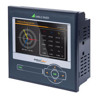
Camille Bauer SINEAX AM2000 Operating Instructions Manual (118 pages)
Brand:
Camille Bauer
| Category:
Controller
| Size: 10 MB
Table of Contents
Table of Contents
3
1 Introduction
5
Purpose of this Document
5
Scope of Supply
5
Further Documents
5
2 Safety Notes
6
3 Device Overview
6
Brief Description
6
Device Overview
7
Available Measurement Data
8
4 Mechanical Mounting
9
Panel Cutout
9
Panel Mounting of the Device
9
Hat Rail Mounting AM1000
10
Demounting of the Device
10
5 Electrical Connections
11
General Safety Notes
11
Terminal Assignments of the I/O Extensions of AM2000/3000
12
Possible Cross Sections and Tightening Torques
13
Inputs
14
Power Supply
26
Relays
26
Digital Inputs
26
Digital Outputs
28
Analog Outputs
29
Modbus Interface RS485
29
Fault Current Detection
31
Temperature Inputs
33
Uninterruptible Power Supply (UPS), AM3000 Only
33
GPS Time Synchronization
34
6 Commissioning
36
Parametrization of the Device Functionality
37
Operating LED of AM1000 Without Display
37
Installation Check
37
Ethernet Installation
39
Settings
39
Connection of the Standard Interface
42
Connection of the IEC61850 Interface
42
Connection of the PROFINET Interface
42
MAC Addresses
43
Resetting the Communication Settings of an AM1000 Without Display
44
Communication Tests
44
IEC 61850 Interface
44
PROFINET IO Interface
45
General Stations Description File (GSD)
45
Parameterization of the Device
46
Validity of Measurements
47
PROFINET State
48
Simulation of Analog / Digital Outputs
49
Security System
49
RBAC Management
50
User Log in / out Via Website
53
User Log in / out Via Local Display
54
Simple Password Protection
55
Whitelisting Clients
56
Secure Communication Using Https
56
Audit Log (SYSLOG)
57
7 Operating the Device
59
Operating Elements
59
Selecting the Information to Display
59
Measurement Displays and Used Symbols
60
Resetting Measurement Data
62
Configuration
62
Configuration at the Device
62
Configuration Via Web Browser
64
Alarming
66
Limit Values on Base Quantities
66
Monitoring Fault-Currents
67
Temperature Monitoring
68
Monitoring Functions
69
Summary Alarm
70
Data Recording
71
Periodic Data
71
User-Defined Events
74
Disturbance Recorder (AM1000 / AM3000 Only)
76
Micro SD Card (AM2000/3000 Only)
79
Measurement Information in File Format
80
Creating Periodic File Data
80
Accessing File Information Via Webpage
81
Periodical Sending to a SFTP Server
82
Timeouts
82
8 Service, Maintenance and Disposal
83
Calibration and New Adjustment
83
Cleaning
83
Battery
83
Disposal
83
9 Technical Data
84
10 Dimensional Drawings
91
Annex
93
A Description of Measured Quantities
93
A1 Basic Measurements
93
A2 Harmonic Analysis
97
A3 System Imbalance
98
A4 Mean Values and Trend
99
A5 Meters
100
B Display Matrices
101
B0 Used Abbreviations for the Measurements
101
B1 Display Matrices for Single Phase System
106
B2 Display Matrices for Split-Phase (Two-Phase) Systems
107
B3 Display Matrices for 3-Wire System, Balanced Load
108
B4 Display Matrices for 3-Wire System, Balanced Load, Phase Shift
109
B5 Display Matrices for 3-Wire Systems, Unbalanced Load
110
B6 Display Matrices for 3-Wire Systems, Unbalanced Load, Aron
111
B7 Display Matrices for 4-Wire System, Balanced Load
112
B8 Display Matrices for 4-Wire Systems, Unbalanced Load
113
B9 Display Matrices for 4-Wire System, Unbalanced Load, Open-Y
114
B10 Common Display Matrices
115
C Logic Functions
116
DFCC Statement
117
Index
118
Advertisement
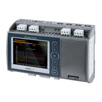
Camille Bauer SINEAX AM2000 Operating Instructions Manual (90 pages)
Device handbook
Brand:
Camille Bauer
| Category:
Measuring Instruments
| Size: 11 MB
Table of Contents
Table of Contents
3
1 Introduction
5
Purpose of this Document
5
Scope of Supply
5
Further Documents
5
2 Safety Notes
6
3 Device Overview
6
Brief Description
6
Available Measurement Data
6
4 Mechanical Mounting
7
Linax Pq3000
7
Linax Pq5000
8
5 Electrical Connections
9
General Safety Notes
9
Terminal Assignments of the I/O Extensions
10
Linax Pq3000
10
Linax Pq5000
11
Possible Cross Sections and Tightening Torques
11
Inputs
12
Power Supply
19
Relays
19
Digital Inputs
19
Digital Outputs
20
Analog Outputs
21
Fault Current Detection
22
Modbus Interface RS485
24
Uninterruptible Power Supply (UPS)
24
GPS Time Synchronization
25
6 Commissioning
27
Parametrization of the Device Functionality
28
Operating LED (PQ5000 Only)
28
Installation Check
28
Ethernet Installation
30
Settings
30
Connection of the Standard Interface
32
Connection of the IEC61850 Interface
33
MAC Addresses
33
Communication Tests
34
Resetting the Communication Settings of the PQ5000
34
Simulation of Analog / Digital Outputs
34
Protection against Device Data Changing
35
7 Operating the Device
36
Operating Elements
36
Selecting the Information to Display
36
Measurement Displays and Used Symbols
37
Resetting Measurement Data
39
Configuration
39
Configuration at the Device
39
Configuration Via Web Browser
40
PQ Monitoring
42
PQ Events
42
PQ Statistic
43
Provision of PQ Data
43
Alarming
44
Limit Values on Base Quantities
44
Monitoring Fault-Currents
45
Monitoring Functions
46
Summary Alarm
47
Data Recording
48
Periodical Data
48
Events
51
PQ Events
52
PQ Statistic
54
Micro SD Card (PQ3000 Only)
56
Data Export of PQDIF Files
57
Provision of PQ Data
57
Accessing PQDIF Files
57
Evaluation of the PQDIF Files
58
Timeouts
59
8 Service, Maintenance and Disposal
60
Calibration and New Adjustment
60
Cleaning
60
Battery
60
Disposal
60
9 Technical Data
61
10 Dimensional Drawings
68
Annex
69
A Description of Measured Quantities
69
A1 Basic Measurements
69
A2 Harmonic Analysis
73
A3 System Imbalance
74
A4 Mean Values and Trend
75
A5 Meters
76
B Display Matrices
77
B0 Used Abbreviations for the Measurements
77
B1 Display Matrices for Single Phase System
82
B2 Display Matrices for Split-Phase (Two-Phase) Systems
83
B3 Display Matrices for 3-Wire System, Balanced Load
83
B4 Display Matrices for 3-Wire Systems, Unbalanced Load
85
B5 Display Matrices for 3-Wire Systems, Unbalanced Load, Aron
86
B6 Display Matrices for 4-Wire Systems, Unbalanced Load
87
C Logic Functions
88
D FCC Statement
89
Index
90
Camille Bauer SINEAX AM2000 Device Handbook (62 pages)
Brand:
Camille Bauer
| Category:
Measuring Instruments
| Size: 3 MB
Table of Contents
Table of Contents
3
1 Introduction
5
Purpose of this Document
5
Scope of Supply
5
Further Documents
5
2 Safety Notes
6
3 Device Overview
6
Brief Description
6
Available Measurement Data
6
4 Mechanical Mounting
7
Panel Cutout
7
Mounting of the Device
7
Demounting of the Device
7
5 Electrical Connections
8
General Safety Notes
8
Terminal Assignments of the I/O Extensions
9
Possible Cross Sections and Tightening Torques
9
Inputs
10
Power Supply
19
Relays
19
Digital Inputs and Outputs
19
Analog Outputs
20
Modbus Interface RS485
21
6 Commissioning
22
Parametrization of the Device Functionality
22
Installation Check
23
Simulation of I/Os
23
7 Operating the Device
24
Operating Elements
24
Selecting the Information to Display
24
Measurement Displays and Used Symbols
25
Alarming
27
Resetting Measurements
29
Setting / Resetting of Meter Contents
29
Configuration
29
Timeouts
30
Calibration and New Adjustment
31
Cleaning
31
Battery
31
Disposal
31
9 Technical Data
32
10 Dimensional Drawings
38
Annex
39
A Description of Measured Quantities
39
A1 Basic Measurements
39
A2 Harmonic Analysis
43
A3 System Imbalance
44
A4 Mean Values and Trend
45
A5 Meters
46
B Display Matrices
47
B0 Used Abbreviations for the Measurements
47
B1 Display Matrices for Single Phase System
51
B2 Display Matrices for Split-Phase (Two-Phase) Systems
52
B3 Display Matrices for 3-Wire System, Balanced Load
53
B4 Display Matrices for 3-Wire Systems, Unbalanced Load
54
B5 Display Matrices for 3-Wire Systems, Unbalanced Load, Aron
55
B6 Display Matrices for 4-Wire System, Balanced Load
56
B7 Display Matrices for 4-Wire Systems, Unbalanced Load
57
B8 Display Matrices for 4-Wire System, Unbalanced Load, Open-Y
58
C Logic Functions
59
D Declaration of Conformity
60
D1 CE Conformity
60
D2 FCC Statement
61
Index
62
Advertisement
Advertisement
Related Products
Camille Bauer APLUS
Camille Bauer SINEAX AM3000
Camille Bauer APLUS-TFT
Camille Bauer SINEAX CAM
Camille Bauer SINEAX DM5 Series
Camille Bauer SINEAX DM5S
Camille Bauer SINEAX DM5F
Camille Bauer SINEAX DM5000
Camille Bauer SINEAX DME 400 Series
Camille Bauer SINEAX DME 400-1
Camille Bauer Categories
Transducer
Measuring Instruments
Transmitter
Amplifier
Transformer
More Camille Bauer Manuals
Login
Sign In
OR
Sign in with Facebook
Sign in with Google
Upload manual
Upload from disk
Upload from URL