Table of Contents
Advertisement
Available languages
Available languages
Quick Links
Advertisement
Table of Contents

Related Manuals for Fermax AC-MAX KIT 2 DOORS


Summary of Contents for Fermax AC-MAX KIT 2 DOORS
- Page 1 ISTEMA DE CONTROL DE ACCESO Kits AC-MAX 2/4 puertas Manual de instrucciones Cód. 970073EIPb Versión del producto: 1.1 Versión de firmware: 1.7.2 o posterior Versión de documento: Rev. A Manuales y software v2.0 disponible en www.fermax.com a través del código QR (1) adjunto,...
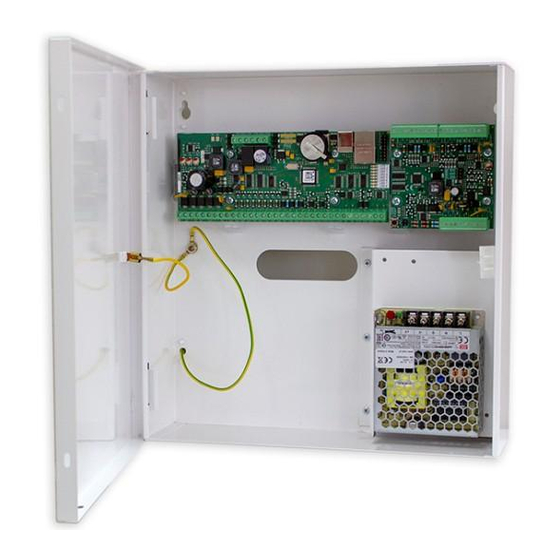
- Page 2 970073EIPb V04_21 NTRODUCCIÓN Los kits AC-MAX ref. 5223 y 5224 están compuestos del siguiente material: Ref. 5223 (95943c o superior) KIT AC-MAX-CU 2 PUERTAS. -Caja metálica BOX-IP15 -Alimentador PWR2D. -Unidad de control AC-MAX-CU. -Expansor de 2 puertas. EXP2D. Ref. 5224 (95944c o superior) KIT AC-MAX-CU 4 PUERTAS. -Caja metálica BOX-IP16 -Alimentador PWR4D.
- Page 3 970073EIPb V04_21 El KIT AC-MAX 2 PUERTAS (Fig. 1) permite: 2 puertas con 2 lectores Wiegand (1 lector Wiegand de entrada, por puerta) 2 puertas con 4 lectores Wiegand (1 lector Wiegand de entrada y 1 lector Wiegand de salida, por puerta) 2 puertas con 2 lectores de huella (RS485) (1 lector de huella (RS485) de entrada, por puerta) 2 puertas con 4 lectores de huella (RS485) (1 lector de huella (RS485) de entrada y 1 lector...
- Page 4 970073EIPb V04_21 Fig.4 Esquema de conexión de alimentación del expansor y de la central AC-MAX) con lectores de huella RS485 (kit ref.5223). Puerta 1- Puerta 4 Fig.5 Esquema de conexión de alimentación del expansor y de la central AC-MAX con lectores Wiegand (kit ref.5224).
- Page 5 970073EIPb V04_21 AC-MAX ISTEMA DE CONTROL DE ACCESO Unidad de Control AC-MAX_CU 2/4 puertas Manual de instrucciones Cód. 970073EIPb Versión del producto: 1.1 Versión de firmware: 1.7.2 o posterior Versión de documento: Rev. A 5/30...
- Page 6 970073EIPb V04_21 NTRODUCCIÓN AC-MAX CU es un módulo electrónico que realiza la función de Unidad de Control que se incluye en los kits del sistema AC-MAX. ONFIGURACIÓN Para utilizar la AC-MAX_CU en el sistema de control de accesos es necesario realizar dos pasos de configuración: •...
- Page 7 970073EIPb V04_21 ONFIGURACIÓN DE BAJO NIVEL La configuración de bajo nivel es necesaria para ajustar los parámetros del circuito AC-MAX_CU y debe realizarse después de que la Unidad de Control AC-MAX_CU se registre en el software AC-MAX LT/ST. Durante la primera configuración de bajo nivel se configuran la dirección IP propia y la clave de comunicación.
- Page 8 970073EIPb V04_21 Pulse Siguiente y Ejecutar descubrimiento de recursos Hardware y finalizar. NOTA: Si no sabe la IP actual de su controlador o su clave de comunicación puede restablecer la memoria de la Unidad de Control a valores de fábrica. 3.
- Page 9 970073EIPb V04_21 4. Configuraremos la Unidad de Control los nuevos parámetros Dirección IP y programe los demás parámetros según sea necesario y al finalizar haremos un clic en Enviar al dispositivo. 5. Después iremos a la pestaña Bus RS-485 Y detectará todos los dispositivos conectados en el BUS A1, B1 de la unidad de Control. 9/30...
- Page 10 970073EIPb V04_21 Una vez Cerrada la ventana veremos los dispositivos detectados y podremos configurarlos en bajo nivel. Tanto la dirección RS-485, como las salidas y entradas necesarias. Esto será posible si por ejemplo los EXP2D/4D tienen un jumper puesto entre los pines MEM. Si no lo tuvieran no dejaría configurar estos dispositivos en bajo nivel.
- Page 11 970073EIPb V04_21 En el caso del EXP8I/O deben tener un jumper entre los pines de JP7. Si este expansor ya tiene Jumpers que configuran la dirección aunque se cambie desde el software permanecerá la dirección establecida por los Jumpers. Si quiere realizar la configuración desde el software deberá dejar únicamente el jumper JP7 para poder entrar en configuración de bajo nivel y establecer la dirección RS-485 que se desee a través de la red.
- Page 12 970073EIPb V04_21 6. Al cerrar nos consultará si queremos inicializar el dispositivo le diremos que Sí. 12/30...
- Page 13 970073EIPb V04_21 Y pulsaremos Ejecutar y al finalizar Cerrar. ESTABLECIMIENTO DE LA MEMORIA El procedimiento de restablecimiento de la memoria borra todos los ajustes de la configuración de bajo nivel, incluida la clave de comunicación (ninguna) y la dirección IP predeterminada de la Unidad Central (192.168.0.213).
- Page 14 970073EIPb V04_21 9. Después dar a ok. Y volver a configurar eb bajo nivel para enviar de nuevo las tablas. 14/30...
-
Page 15: Actualización Del Firmware
Nota: Durante el proceso de actualización del firmware, es necesario garantizar una alimentación continua y estable para el módulo AC-MAX_CU. Un fallo de la fuente de alimentación puede dar lugar a la reparación del dispositivo por parte del servicio Fermax. 15/30... - Page 16 970073EIPb V04_21 LIMENTACIÓN El módulo AC-MAX_CU requiere alimentación de 12 Vcc. RS-485 Cada módulo o dispositivo conectado al bus RS-485 de AC-MAX_CU debe tener la dirección única establecida en el intervalo 100-115. Todas las fuentes de alimentación utilizadas para alimentar los módulos y dispositivos conectados al mismo bus RS485 deben estar conectadas por medio de cables específicos (separados) de cualquier diámetro y, de manera opcional, conectados a tierra en cualquier punto arbitrariamente seleccionado.
- Page 17 970073EIPb V04_21 TML+ Salida alimentación RS485(1)/ Línea A del expansor, EXP2D 12 Vcc/0,2A, nodo positivo o EXP4D Entrada WG IN1 D0 RS485(1)/Línea B del expansor, EXP2D o EXP4D Entrada WG IN2 D1 Salida de transistor Tierra Salida de transistor Entrada WG IN3 D0 Tierra Entrada WG IN4 D1 x SIN FUNCIÓN...
-
Page 18: Esquema De Instalación
970073EIPb V04_21 Clase ambiental Clase I, condiciones generales de interior, temperatura: +5°C a +40 °C, humedad relativa: 10 a 95 % (sin condensación) (de acuerdo con EN 50131-1) Dimensiones (Alto x Ancho x 72 x 175 x 30 mm Profundo) Peso aprox. - Page 19 970073EIPb V04_21 AC-MAX ISTEMA DE CONTROL DE ACCESO Expansor de E/S EXP2D (Kit 5223) /4D (kit 5224) Manual de instrucciones Cód. 970073EIPb Versión del producto: 1.1 Versión de firmware: 1.1.30.260 Versión de documento: Rev. A 19/30...
- Page 20 970073EIPb V04_21 Introducción (EXP2D/EXP4D) EXP2D/4D es un expansor de E/S destinado al control de dos/cuatro puertas con lectores de huella AC- MAX (RS485) o lectores wiegand. Además, el expansor funciona como distribuidor de la fuente de alimentación de 12 Vcc y del bus RS485. El EXP2D/4D ofrece dos/cuatro entradas, dos/cuatro salidas, una interfaz RS485, una fuente de alimentación principal de 1 A y fuente de alimentación auxiliar de 0,2 A para cada puerta.
-
Page 21: Fuente De Alimentación
970073EIPb V04_21 El KIT AC-MAX 2 PUERTAS (Fig.10) permite: 2 puertas con 2 lectores Wiegand (1 lector Wiegand de entrada, por puerta) 2 puertas con 4 lectores Wiegand (1 lector Wiegand de entrada y 1 lector Wiegand de salida, por puerta) 2 puertas con 2 lectores de huella (RS485) (1 lector de huella (RS485) de entrada, por puerta) 2 puertas con 4 lectores de huella (RS485) (1 lector de huella (RS485) de entrada y 1 lector lector de huella de salida, por puerta) - Page 22 970073EIPb V04_21 Fig. 12 Distribución del bus RS485 de la unidad central AC-MAX (RS485) a los lectores de huella FPAC- MAX ref. 5225. Fig.13 Conexión puerta 1, con lector de entrada y lector de salida FPAC-MAX (RS485) ref. 5225. * Este lector de huella se alimenta directamente de la fuente del kit o de la salida auxiliar del expansor.
- Page 23 970073EIPb V04_21 Entradas DC y DR DC y DR son entradas paramétricas que pueden configurarse como tipo NO, NC. También es posible configurar el tiempo de respuesta de entrada que define el pulso mínimo que puede activar la entrada. La configuración de los parámetros eléctricos de entrada se realiza dentro de la configuración de bajo nivel por medio del software AC-MAX solo como NO o NC.
- Page 24 970073EIPb V04_21 Conexión del expansor a la Unidad de Control En la siguiente figura, desde el expansor no sólo se alimenta la central, sino también puertas, y vemos como se conecta la batería (opcional) al expansor. EXP2D/EXP4D. * Estos lectores se alimentan directamente de la fuente del kit, si consumen individualmente más de 100mA.
- Page 25 970073EIPb V04_21 Salidas de alimentación TML La salida TML está dedicada a la alimentación de lectores de las puertas. El terminal TML+ está protegido con un fusible electrónico de 0,2 A. El terminal TML- tiene un cortocircuito interno a masa. El indicador LED verde se encuentra en el terminal TML+ para señalar la tensión en la salida.
-
Page 26: Instalación
970073EIPb V04_21 Nota: Para programar la dirección "100" espere 16 parpadeos. Instalación Todas las conexiones eléctricas deben realizarse sin tensión en los cables/terminales y con la fuente de alimentación desconectada. La sección transversal de los cables de alimentación debe ser adecuada para evitar caídas de tensión superiores a 200 mV de carga nominal. - Page 27 970073EIPb V04_21 Configuración de carga de la batería Se recomienda una corriente de 300 mA para una batería de 12 V/7 Ah Se recomienda una corriente de 600 mA para una batería de 12 V/17 Ah Señalización LED En el Modo normal , el LED indica la falta de alimentación externa. En caso de Restablecimiento de la memoria , el LED se utiliza para el direccionamiento manual.
- Page 28 970073EIPb V04_21 TMLx- Polo negativo de salida de alimentación de 13,8 Vcc/0,2 A Bus de comunicación de salida RS485, línea A (conectar si hay lectores de huella) Bus de comunicación de salida RS485, línea B (conectar si hay lectores de huella) LCKx Abrepuertas.
- Page 29 970073EIPb V04_21 Especificaciones EXP2D/4D Parámetro Valor EXP2D // EXP4D Tensión de la fuente de alimentación 13,8 Vcc; +/- 100 mV (batería de reserva conectada) 11-15 Vcc (sin batería de reserva) Corriente de la fuente de alimentación Expansor: 50 mA Expansor con carga máxima en las salidas de potencia y corriente de carga de batería máxima de Ref.
-
Page 30: Declaración De Conformidad Ce
V04_21 DECLARACIÓN DE CONFORMIDAD CE Por medio de la presente, FERMAX ELECTRÓNICA, S.A.U. declara que la ref. 5223-5224 KIT CONTROLADOR AC-MAX 2-4 PUERTAS, cumple con los requisitos de la Directiva RED 2014/53/UE y de la Directiva RoHS 2011/65/EU. Ver página web www.fermax.com... -
Page 31: Installer Manual
AC-MAX A CCESS ONTROL YSTEM AC-MAX KITS 2/4 doors Installer Manual Cod. 970073EIPb Product version: 1.1 Firmware version: 1.7.2 or newer Document version: Rev. A The manuals and software v2.0 are available at www.fermax.com or via the attached QR (1) code. - Page 32 Cod. 970073EIPb V04_21 NTRODUCTION The AC-MAX kits ref. 5223 and 5224 are composed of the following material: Ref. 5223 (95943c or newer) KIT AC-MAX-CU 2 DOORS. -Metal box BOX-IP15 -Power Supply PWR2D. -Controller Unit AC-MAX-CU. -Expansor 2 doors. EXP2D. Ref. 5224 (95944c o newer) KIT AC-MAX-CU 4 DOORS. -Metal box BOX-IP16 -Power Supply PWR4D.
-
Page 33: Installation
Cod. 970073EIPb V04_21 The KIT AC-MAX 2 DOORS (Fig. 1) allows: 2 doors with 2 Wiegand readers (1 Wiegand input reader, per door) 2 doors with 4 Wiegand readers (1 Wiegand input reader and 1 Wiegand output reader, per door) 2 doors with 2 fingerprint readers (RS485) (1 fingerprint reader (RS485) input, per door) 2 doors with 4 fingerprint readers (RS485) (1 input fingerprint reader (RS485) and 1 reader reader output footprint, per door) - Page 34 Cod. 970073EIPb V04_21 Fig.5 Power supply diagram of the expander and the AC-MAX control unit with Wiegand readers (kit ref.5224). Fig.6 Power supply diagram of the expander and the AC-MAX control unit with RS485 fingerprints readers (kit ref.5224). * These fingerprint readers feed directly from the kit power supply. 4/30...
- Page 35 Cod. 970073EIPb V04_21 AC-MAX A CCESS ONTROL YSTEM AC-MAX_CU Cotroller Unit 2/4 doors Installer Manual Cod. 970073EIPb Product version: 1.1 Firmware version: 1.7.2 or newer Document version: Rev. A 5/30...
- Page 36 Cod. 970073EIPb V04_21 NTRODUCTION AC-MAX is a electronic module used in AC-MAX system can function as access Controller Unit. ONFIGURATION To use the AC-MAX_CU in the access control system, two configuration steps are necessary: Low level configuration and high level configuration using the software. Low-level configuration allows adapting the AC-MAX electronic module in terms of IP address, inputs, outputs and other parameters that affect the AC-MAX software properties and system logic.
-
Page 37: Low Level Configuration
Cod. 970073EIPb V04_21 EVEL ONFIGURATION The low level configuration is necessary to set the parameters of the AC-MAX_CU circuit and must be performed after the AC-MAX_CU Control Unit is registered in the AC-MAX LT/ST software. During the first low level configuration the own IP address and the communication key are configured. The programming of other parameters depends on the requirements of each installation scenario and is not mandatory. - Page 38 Cod. 970073EIPb V04_21 Click Next and Run Hardware Resource Discovery and Finish. NOTE: If you do not know the current IP of your controller or its communication key, you can reset the Control Unit's memory to factory defaults. 1. Right-click on the Control Unit we have just added and select Low Level Configuration. 8/30...
- Page 39 Cod. 970073EIPb V04_21 2. We will configure the Control Unit the new IP Address parameters and program the other parameters as required and when finished we will click on Send to device. 3.Then go to the RS-485 Bus tab. And it will detect all devices connected on BUS A1, B1 of the Control unit. 9/30...
- Page 40 Cod. 970073EIPb V04_21 Once the window is closed, we will see the detected devices and we will be able to configure them in low level. Both the RS-485 address and the necessary inputs and utputs. This will be possible if for example the EXP2D/4D have a jumper placed between the MEM pins. If they don't, it would not allow to configure these devices in low level.
- Page 41 Cod. 970073EIPb V04_21 In the case of the EXP8I/O they must have a jumper between the pins of JP7. If this expander already has jumpers that configure the address, even if it is changed from the software, the address established by the jumpers will remain the same.
- Page 42 Cod. 970073EIPb V04_21 3. When closing it will ask us if we want to initialise the device, we will say Yes. 12/30...
-
Page 43: Memory Reset
Cod. 970073EIPb V04_21 Click on Run and when you finish, click on Close. EMORY ESET Memory Reset procedure erases all low level configuration settings including communication key (none) and default IP address of the Controller Unit (192.168.0.213). Memory Reset Procedure: 1. - Page 44 Cod. 970073EIPb V04_21 Then click ok. And reconfigure low level to send the tables again. 14/30...
-
Page 45: Firmware Upgrade
Cod. 970073EIPb V04_21 IRMWARE PGRADE New firmware can be uploaded to the Central Unit using AC-MAX HW program and selecting Tools -> Update firmware, make a backup of low level configuration and save the settings to file as firmware upgrade usually restores factory default settings and erases communication key. 1. - Page 46 Cod. 970073EIPb V04_21 OWER UPPLY AC-MAX module requires to be supplied from 12Vdc. RS485 B Every module or device connected to the AC-MAX RS485 bus must have the unique address set in 100- 115 range. All power supply sources used to supply modules and devices connected to the same RS485 bus, must be connected by dedicated (separate) wire of any diameter and optionally, grounded in any arbitrary selected point.
- Page 47 Cod. 970073EIPb V04_21 IN1 input WG D0 RS485(1)/ Line B from EXP2D/EXP4D if exist fingerprints readers. IN2 input WG D1 Transistor output Signal ground Transistor output IN3 input WG D0 Signal ground IN4 input WG D1 x NO FUNCTION Signal ground x NO FUNCTION Table 2: Power Supply LEDs Function...
-
Page 48: Installation Diagrams
Cod. 970073EIPb V04_21 Weight approx. 200g Certifications UKCA NSTALLATION IAGRAMS Fig. 9 Connecting Wiegand readers to AC-MAX board. 18/30... - Page 49 Cod. 970073EIPb V04_21 AC-MAX A CCESS ONTROL YSTEM EXP2D (Kit 5223) / EXP4D (kit 5224) I/O expander Installer Manual Cod. 970073EIPb Product version: 1.1 Firmware version: 1.1.30.260 Document version: Rev. A 19/30...
- Page 50 Cod. 970073EIPb V04_21 Introduction EXP2D/4D is I/O expander dedicated to control two doors with AC-MAX readers (RS485) in AC-MAX system. Additionally the expander operates as distributor of 12Vdc power supply and RS485 bus. For each door the EXP2D/4D offers two/four inputs, two/four outputs, RS485 interface, 1.0A main power supply and 0.2A auxiliary power supply.
-
Page 51: Power Supply
Cod. 970073EIPb V04_21 The KIT AC-MAX 2 DOORS (Fig. 10) allows: 2 doors with 2 Wiegand readers (1 Wiegand input reader, per door) 2 doors with 4 Wiegand readers (1 Wiegand input reader and 1 Wiegand output reader, per door) 2 doors with 2 fingerprint readers (RS485) (1 fingerprint reader (RS485) input, per door) 2 doors with 4 fingerprint readers (RS485) (1 input fingerprint reader (RS485) and 1 reader reader output footprint, per door) - Page 52 Cod. 970073EIPb V04_21 Fig. 13 Door 1 connection, with input fingerprint reader and output fingerprint reader FPAC-MAX (RS485) ref. 5225. * This fingerprint reader feeds directly from the kit power supply. LCK and BELL outputs LCK and BELL are transistor (open collector) outputs which can control 15V/1.0A load. In standard scenario of door control, LCK output is dedicated to control door lock while BELL output is dedicated to control alarm signalling device and door bell but they can be used for any other functions which are configured using AC-MAX management software.
-
Page 53: Door Control
Cod. 970073EIPb V04_21 Door control The expander enables distribution of power and RS485 communication bus to two doors. For each door the EXP2D/4D offers 1.0A power supply output (VDR+ and VDR- terminals), 0.2A power supply output (TML+ and TML- terminals), communication bus (RS485 A and B terminals), two programmable inputs (DC and DR) and two programmable outputs (LCK and BELL). - Page 54 Cod. 970073EIPb V04_21 Door 1- Door 4 Fig. 16 Connection diagram for expander and AC-MAX central unit with Wiegand readers (kit ref. 5224) TML power outputs TML is dedicated to supply readers at doors. The terminal TML+ is protected with 0.2A electronic fuse . The terminal TML- is internally shorted to ground.
- Page 55 Cod. 970073EIPb V04_21 Number of LED AC pulses RS485 address Note: In order to program the address „100” wait for 16 LED AC pulses. Installation All electric connections must be done without voltage on wires/terminals and with power supply disconnected. The cross section of power supply wires must be adequate as to avoid voltage drop greater than 200mV for rated load.
- Page 56 Cod. 970073EIPb V04_21 EXP4D Fig. 18 EXP4D board Battery charging settings 300 mA current recommended for 12Vdc/7Ah battery 600 mA current recommended for 12Vdc/17Ah battery LED signalling In Normal mode the LED signals lack of external power supply. In case of Memory reset the LED is used for manual addressing.
- Page 57 Cod. 970073EIPb V04_21 VOUT- 13.8Vdc/0.2A output power negative pole. Connect to AUX - of the AC-MAX_CU Control Unit. AUX+ 13.8Vdc/0.2A output power positive pole AUX- 13.8Vdc/0.2A output power negative pole VIN+ 13.8Vdc input power positive pole. Connect to the output of the PWR2D / 4D to the positive pole.
- Page 58 Cod. 970073EIPb V04_21 Specification EXP2D/4D Parameter Value EXP2D // EXP4D Power supply voltage 13.8Vdc; +/- 100mV (backup battery connected) 11-15 Vdc (no backup battery) Power supply current Expander: 50mA Expander with maximal load at power outputs and maximal battery charging current Ref.
-
Page 59: Ce Declaration Of Conformity
Cod. 970073EIPb V04_21 CE DECLARATION OF CONFORMITY Hereby, FERMAX ELECTRONICA, S.A.U., declares that this KIT AC-MAX CONTROLLER FOR 2-4 DOORS Ref. 5223-5224, is in compliance with the essential requirements of Directive RED 2014/53/UE and Directive RoHS 2011/65/UE. See website www.fermax.com. FERMAX Avd. - Page 60 Cod. 970073EIPb V04_21 30/30...
- Page 61 AC-MAX KITS 2/4 portas Manual do instalador Cod. 970073EIPb Versão do produto: 1.1 Versão firmware: 1.7. 2 ou mais recente Versão do documento: Rev. A Os manuais e o software v2.0 estão disponíveis em www.fermax.com ou através do código (1) anexado.
- Page 62 970073EIPb V04_21 NTRODUÇÃO Os kits AC-MAX ref. 5223 e 5224 são compostos pelo seguinte material: Ref. 5223 (95943c ou mais recente) KIT AC-MAX-CU 2 PORTAS. -Caixa metálica BOX-IP15 - Fonte de alimentação PWR2D. - Unidadede Controlador AC-MAX-CU. - Expansor 2 portas. EXP2D. Ref.
- Page 63 970073EIPb V04_21 O KIT AC-MAX 2 PORTAS (Fig. 1) permite: 2 portas com 2 leitores Wiegand (1 leitor de entrada wiegand, por porta) 2 portas com 4 leitores Wiegand (1 leitor de entrada wiegand e 1 leitor de saída wiegand, por porta) 2 portas com 2 leitores de impressões digitais (RS485) (1 leitor de impressões digitais (RS485) entrada, por porta)
- Page 64 970073EIPb V04_21 Fig.4 Diagrama de alimentação do expansor e da unidade de controlo AC-MAX com leitores de impressões digitais RS485 (kit ref.5223). Fig.5 Diagrama de alimentação do expansor e da unidade de controlo AC-MAX com leitores Wiegand (kit ref.5224). Fig.6 Diagrama de alimentação do expansor e da unidade de controlo AC-MAX com leitores de impressões digitais RS485 (kit ref.5224).
- Page 65 970073EIPb V04_21 AC-MAX ISTEMA DE ONTROLO DE CESSO AC-MAX_CU Cotroller Unidade 2/4 portas Manual do instalador Cod. 970073EIPb Versão do produto: 1.1 Versão firmware: 1.7. 2 ou mais recente Versão do documento: Rev. A 5/30...
- Page 66 970073EIPb V04_21 NTRODUÇÃO AC-MAX é um módulo eletrónico utilizado no sistema AC-MAX que pode funcionar como Unidade de Controlador de Acesso. ONFIGURAÇÃO Para utilizar o AC-MAX_CU no sistema de controlo de acesso, são necessários dois passos de configuração: - Configuração de baixo nível e configuração de alto nível utilizando o software. A configuração de baixo nível permite adaptar o módulo eletrónico AC-MAX em termos de endereço IP, entradas, saídas e outros parâmetros que afetam as propriedades do software AC-MAX e a lógica do sistema.
- Page 67 970073EIPb V04_21 ONFIGURAÇÃO DE BAIXO NÍVEL A configuração de baixo nível é necessária para definir os parâmetros do circuito AC-MAX_CU e deve ser executada após a inscrição da Unidade de Controlo AC-MAX_CU no software AC-MAX LT/ST. Durante a primeira configuração de baixo nível, o próprio endereço IP e a chave de comunicação estão configurados.
- Page 68 970073EIPb V04_21 Clique em Seguida e executar hardware de descoberta e acabamento de recursos de hardware. NOTA:Se não souber o atual IP do seu controlador ou a sua chave de comunicação, pode redefinir a memória da Unidade de Controlo para padrão de fábrica. 1.
- Page 69 970073EIPb V04_21 2. Configuraremos a Unidade de Controlo dos novos parâmetros ip address e programaremos os outros parâmetros conforme necessário e quando terminarmos clicaremos em Enviar para o dispositivo. 3.Em seguida, vá para a conta de ônibus RS-485. E irá detetar todos os dispositivos ligados no BUS A1, B1 da unidade de Controlo. 9/30...
- Page 70 970073EIPb V04_21 Assim que a janela estiver fechada, veremos os dispositivos detetados e poderemos configurá-los em baixo nível. Tanto o endereço RS-485 como as entradas e utposições necessárias. Isto será possível se, por exemplo, o EXP2D/4D tiver uma ponte colocada entre os pinos MEM. Se não o fizerem, não permitirá...
- Page 71 970073EIPb V04_21 No caso do EXP8I/O devem ter um ponte entre os pinos de JP7. Se este expansor já tiver saltadores que configuram o endereço, mesmo que seja alterado a partir do software, o endereço estabelecido pelos jumpers permanecerá o mesmo. Se pretender fazer a configuração a partir do software, tem de deixar apenas a ponte JP7 para poder entrar em configuração de baixo nível e definir o endereço RS-485 desejado através da rede.
- Page 72 970073EIPb V04_21 3. Ao fechar, perguntar-nos-ão se queremos inicializar o dispositivo, diremos sim. 12/30...
- Page 73 970073EIPb V04_21 Clique em Executar e quando terminar, clique em Fechar. ESET DA EMÓRIA O procedimento de reposição da memória apaga todas as definições deinfiguração low level c,incluindo communication (nenhuma) predefinido umddress da Unidade do Controlador (192.168.0.213). Procedimento de reposição da memória: 1.
- Page 74 970073EIPb V04_21 9.Em seguida, clique ok. E reconfigure o nível baixo para enviar as mesas novamente. 14/30...
-
Page 75: Atualização De Firmware
970073EIPb V04_21 TUALIZAÇÃO DE FIRMWARE O novo firmware pode ser carregado para a Unidade Central utilizando o programa AC-MAX HW e selecionando Tools -> Update firmware, make a backup of low level configuration and save the settings to file as firmware upgrade normalmente restaura as definições padrão da fábrica e apaga communication key. -
Page 76: Fornecimento De Energia
970073EIPb V04_21 ORNECIMENTO DE ENERGIA O módulo AC-MAX requer que seja fornecido a partir de 12Vdc. Ô RS485 NIBUS Todos os módulos ou dispositivos ligados ao autocarro AC-MAX RS485 devem ter o endereço único definido na gama 100-115. Todas as fontes de alimentação utilizadas para fornecer módulos e dispositivos ligados ao mesmo autocarro RS485 devem ser ligadas por um fio dedicado (separado) de qualquer diâmetro e opcionalmente, ligados à... - Page 77 970073EIPb V04_21 TML+ 12Vdc/0.2A saída de fornecimento, RS485(1)/ Linha A de EXP2D/EXP4D mais nó se existirem impressões digitais dos leitores. Entrada IN1 WG D0 RS485(1)/ Linha B de EXP2D/EXP4D se existirem leitores de impressões digitais. Entrada IN2 WG D1 Saída transístor Rio GND Terreno de sinal Saída transístor...
- Page 78 970073EIPb V04_21 Porta Ethernet Porta de comunicação 10BASE-T 10/100Mb Comprimentos de arame 1200m para RS485 150m para Wiegand e AC-MAX CLK/DTA Classe ambiental Classe I, condições gerais interiores, temperatura: +5°C a +40°C, humidade relativa: 10 a 95% (sem condensação) (ac. à EN 50131-1) Dimensões H x W x D 72 x 175 x 30 mm Peso...
- Page 79 970073EIPb V04_21 AC-MAX ISTEMA DE ONTROLO DE CESSO EXP2D (Kit 5223) / EXP4D (kit 5224) Expansor de I/O Manual do instalador Cod. 970073EIPb Versão do produto: 1.1 Versão firmware: 1.1. 30. 260 Versão do documento: Rev. A 19/30...
- Page 80 970073EIPb V04_21 Introdução EXP2D/4D é um expansor de I/O dedicado a controlar duas portas com leitores AC-MAX (RS485) no sistema AC-MAX. Adicionalmente, o expansor funciona como distribuidor de alimentação de 12Vdc e autocarro RS485. Para cada porta o EXP2D/4D oferece duas/quatro entradas, duas/quatro saídas, interface RS485, alimentação principal 1.0A e alimentação auxiliar de 0,2A.
- Page 81 970073EIPb V04_21 O KIT AC-MAX 2 PORTAS (Fig. 10)permite: 2 portas com 2 leitores Wiegand (1 leitor de entrada wiegand, por porta) 2 portas com 4 leitores Wiegand (1 leitor de entrada wiegand e 1 leitor de saída wiegand, por porta) 2 portas com 2 leitores de impressões digitais (RS485) (1 leitor de impressões digitais (RS485) entrada, por porta)
- Page 82 970073EIPb V04_21 Fig. 13 Ligação porta 1, com leitor de impressões digitais de entrada e leitor de impressões digitais de saída FPAC-MAX (RS485) ref. 5225. * Este leitor de impressões digitais alimenta-se diretamente da fonte de alimentaçãodo kit. Saídas LCK e BELL LCK e BELL são saídas transístor (coletor aberto) que podem controlar a carga de 15V/1.0A.
- Page 83 970073EIPb V04_21 Controlo da porta O expansor permite a distribuição de energia e o autocarro de comunicação RS485 para duas portas. Para cada porta, o EX2D/4D oferece saída de alimentação de 1,0A (terminais VDR+ e VDR), saída de alimentação de 0,2A (terminais TML+ e TML), autocarro de comunicação (terminais RS485 A e B), duas entradas programáveis (DC e DR) e duas saídas programáveis (LCK e BELL).
- Page 84 970073EIPb V04_21 Porta 1/Porta 2 Fig. 15 Diagrama de conexão para expansor e unidade central AC-MAX com leitores Wiegand (kit ref. 5223) Porta 1- Porta 4 Fig. 16 Diagrama de conexão para unidade central expansor e AC-MAX com leitores Wiegand (kit ref. 5224) Saídas de energia TML A TML dedica-se a fornecer leitores às portas.
- Page 85 970073EIPb V04_21 Reposição da memória EXP: 1. Desligue a alimentação 2. Linhas LCK1 e DC1 curtas, remova a ponte dos contactos MEM. 3. Ligue a alimentação e coloque a ponte nos contactos MEM dentro de 5 segundos. 4. O DCL LED pulsará. 5.
- Page 86 970073EIPb V04_21 EXP2D Fig. 17 Placa EXP2D EXP4D EXP2D Fig. 18 Placa EXP4D Definições de carregamento de bateria Corrente de 300 mA recomendada para bateria de 12Vdc/7Ah Corrente de 600 mA recomendada para bateria de 12Vdc/17Ah Sinalização LED No modo normal, o LED sinaliza falta de alimentação externa.
- Page 87 970073EIPb V04_21 Pulsação lenta (0,5s/0,5s): Sem comunicação com central Pulsação muito lenta (1s/1s): Erro de memória de configuração Transmissão de dados para o controlador Dados recebidos do controlador Terminais EXP2D/4D Terminal Função BAT+ Polo positivo da bateria O BAT... Polo negativo da bateria VOUT+ 13.8Vdc/0.2A polo positivo de potência de saída.
- Page 88 970073EIPb V04_21 Bloqueio LCK Sino-sino Contacto da porta Libertação da porta Especificação EXP2D/4D Parâmetro Valor EXP2D // EXP4D Tensão de alimentação 13.8Vdc; +/- 100mV (bateria de reserva ligada) 11-15 Vdc (sem bateria de reserva) Corrente de fornecimento de energia Expansor: 50mA Expansor com carga máxima nas saídas de energia e corrente máxima de carregamento de bateria Ref.
- Page 89 970073EIPb V04_21 Informação Produto Descrição EXP2D Expansor de I/O EXP4D Expansor de I/O 29/30...
- Page 90 970073EIPb V04_21 Declaração ce de conformidade POR ESTE MEIO, FERMAX ELECTRONICA, S.A.U. , declara que este KIT AC-MAX CONTROLLER PARA 2-4 PORTAS Ref. 5223-5224, requisitos está em conformidade essenciais da Diretiva RED 2014/53/UE e da Diretiva RoHS 2011/65/UE. Consulte o site www.fermax.com.
Need help?
Do you have a question about the AC-MAX KIT 2 DOORS and is the answer not in the manual?
Questions and answers