Bosch VG4 Series Installation Manual
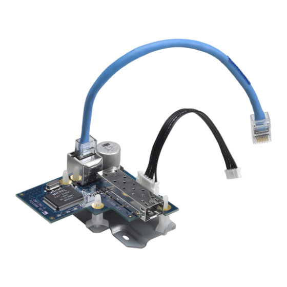
Fiber optic media converter
Hide thumbs
Also See for VG4 Series:
- Installation manual (108 pages) ,
- Firmware update manual (42 pages) ,
- Manual (36 pages)

Related Manuals for Bosch VG4 Series


Summary of Contents for Bosch VG4 Series
- Page 1 All manuals and user guides at all-guides.com VG4 Fiber Optic Media Con- verter VG4-SFPSCKT Installation Guide...
- Page 2 All manuals and user guides at all-guides.com...
-
Page 3: Table Of Contents
Table of Contents | en Table of Contents Important Safety Instructions Customer Support and Service Installing the Fiber Optic Module Description Using an SFP Module Parts Included Installation Instructions Troubleshooting Bosch Security Systems, Inc. Installation Guide F.01U.134.924 | 1.0 | 2009.09... - Page 4 All manuals and user guides at all-guides.com en | Table of Contents Fiber Optic Media Converter F.01U.134.924 | 1.0 | 2009.09 Installation Guide Bosch Security Systems, Inc.
-
Page 5: Important Safety Instructions
12. Install in accordance with the manufacturer's instructions in accordance with applicable local codes. Use only attachments/accessories specified by the manufacturer. Equipment change or modification could void the user's guarantee or authorization agreement. Bosch Security Systems, Inc. Installation Guide F.01U.134.924 | 1.0 | 2009.09... - Page 6 You can view and print the full version of this Installation Manual with Adobe Acrobat Reader. This user guide is the intellectual property of Bosch Security Systems; protected by copyright. F.01U.134.924 | 1.0 | 2009.09 Installation Guide...
-
Page 7: Customer Support And Service
All manuals and user guides at all-guides.com Fiber Optic Media Converter Important Safety Instructions | en Customer Support and Service If this unit needs service, contact the nearest Bosch Security Systems Service Center for authorization to return and shipping instructions. Service Centers... - Page 8 | Important Safety Instructions Fiber Optic Media Converter Warranty and more information For additional information and warranty queries, please contact your Bosch Security Systems representative or visit our website at www.boschsecurity.com. F.01U.134.924 | 1.0 | 2009.09 Installation Guide Bosch Security Systems, Inc.
-
Page 9: Installing The Fiber Optic Module
Fiber Optic Media Converter Installing the Fiber Optic Module | en Installing the Fiber Optic Module This guide provides instructions for installing the Bosch VG4- SFPSCKT Fiber Optic module into a VG4-A-PA1, VG4-A-PA2, VG4-A-PSU1 or a VG4-A-PSU2 AutoDome power supply box. -
Page 10: Using An Sfp Module
The following chart lists the compatibility between the SFP modules: SFP Sub-module used in Use this SFP Sub-module VG4-SFPSCKT in CNFE2MC SFP-2 SFP-2 SFP-3 SFP-3 SFP-23 SFP-24 SFP-24 SFP-23 SFP-25 SFP-26 SFP-26 SFP-25 F.01U.134.924 | 1.0 | 2009.09 Installation Guide Bosch Security Systems, Inc. -
Page 11: Parts Included
Metal adaptor base plate F.01U.072.866 Power harness (black) F.01U.026.085 Four (4) Plastic standoff pins F.01U.073.233 Ethernet patch cable (blue) with F.01U.032.132 RJ45 connectors One (1) M2.5 Phillips pan screw F.01U.009.951 Bosch Security Systems, Inc. Installation Guide F.01U.134.924 | 1.0 | 2009.09... -
Page 12: Installation Instructions
Turn off the power to the VG4 power supply box and remove the cover. Remove the 6-pin connector from the P106 connector inside the power supply box, if present. Figure 2.1 P106 connector with 100 Ohm resistor F.01U.134.924 | 1.0 | 2009.09 Installation Guide Bosch Security Systems, Inc. - Page 13 Figure 2.2 Insert standoff pin into power supply board Connect the supplied power harness (black) to the J103 socket on the power supply board, located below the Heater connector. Figure 2.3 J103 socket location Bosch Security Systems, Inc. Installation Guide F.01U.134.924 | 1.0 | 2009.09...
- Page 14 Secure the base plate with the supplied screw in the lower left hole of the P105 connector. Figure 2.5 Attach base place to power supply box F.01U.134.924 | 1.0 | 2009.09 Installation Guide Bosch Security Systems, Inc.
- Page 15 Figure 2.6 Attach Fiber Optic board to base plate 11. Attach the supplied power harness (black) to its connector on the fiber optic module. Bosch Security Systems, Inc. Installation Guide F.01U.134.924 | 1.0 | 2009.09...
- Page 16 14. Plug the fiber optic cable (LC or SC connector) into the SFP module inside the power supply unit. 15. Close and secure the power supply box when finished. 16. Restore the power to the power supply box. F.01U.134.924 | 1.0 | 2009.09 Installation Guide Bosch Security Systems, Inc.
-
Page 17: Troubleshooting
If the LED is Flashing Red, then Check the fiber connection to the CNFE2MC: – If the Link/Act LED is not lit, then the fiber link is missing. Bosch Security Systems, Inc. Troubleshooting F.01U.134.924 | 1.0 | 2009.09... - Page 18 – If no LED lit on the RJ-45 connector, then there is a fault with this connector, the RJ-45 cable, or the cable is not connected to the VG4-SFPSCKT. F.01U.134.924 | 1.0 | 2009.09 Installation Guide Bosch Security Systems, Inc.
- Page 19 All manuals and user guides at all-guides.com...
- Page 20 Phone: + 31 40 2577 284 Telephone +1 888-289-0096 Fax: +65 6319 3499 Fax: +31 40 2577 330 +1 585-223-9180 apr.securitysystems@bosch.com emea.securitysystems@bosch.com Email: www.boschsecurity.com www.boschsecurity.com security.sales@us.bosch.com www.boschsecurity.us © Bosch Security Systems, Inc. 2009; F.01U.134.924 | 1.0 | 2009.09; Data subject to change without notice.
Need help?
Do you have a question about the VG4 Series and is the answer not in the manual?
Questions and answers