Bosch VG4-SFPSCKT Installation Manual
Fiber optic ethernet media converter kit
Hide thumbs
Also See for VG4-SFPSCKT:
- Installation manual (20 pages) ,
- Installation manual (20 pages) ,
- Installation manual (20 pages)
Advertisement
Advertisement
Table of Contents

Related Manuals for Bosch VG4-SFPSCKT


Summary of Contents for Bosch VG4-SFPSCKT
- Page 1 Fiber Optic Ethernet Media Converter Kit VG4-SFPSCKT Installation Manual...
- Page 3 Table of Contents | en Table of contents Important Safety Instructions Parts List System overview Install for an AUTODOME camera Install for a MIC analog camera Install for an EXTEGRA IP 9000 FX camera Troubleshooting Bosch Security Systems Installation Manual 2015.03 | |...
-
Page 4: Important Safety Instructions
You can view and print the full version of this Installation Manual with Adobe Acrobat Reader. This user guide is the intellectual property of Bosch Security Systems; protected by copyright. 2015.03 | |... -
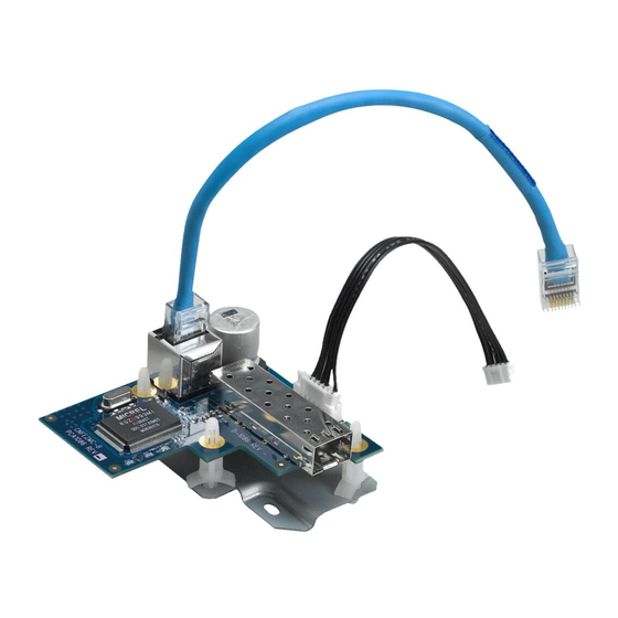
Page 5: Parts List
(with SFP socket) Metal adapter plate F.01U.138.662 Power harness (black) F.01U.026.085 Four (4) Plastic standoff pins F.01U.073.233 Ethernet patch (jumper) cable (blue) F.01U.032.132 with RJ45 connectors One (1) M2.5 Phillips pan screw F.01U.009.951 Bosch Security Systems Installation Manual 2015.03 | |... - Page 6 For a MIC camera, the following parts are included in the kit of the fiber optic module: Part Description Part Number Fiber Optic Media Converter Module F.01U.139.350 Fiber cable (gray) F.01U.xxx.xxxx Two (2) Metal standoff pins F.01U.073.233 Ethernet patch cable (blue) with F.01U.032.132 RJ45 connectors 2015.03 | | Installation Manual Bosch Security Systems...
-
Page 7: System Overview
MIC IP power supply units: MIC-IP-PS-115, MIC-IP-PS-24, MIC-IPIR- PS-115, MIC-IPIR-PS-230, MIC-IPIR-PS-24. The VG4-SFPSCKT is a unique media converter module for use with a VG4 or VG5 series AutoDome incorporating the Ethernet (TCP/IP) Communications Module, or with a MIC IP power supply unit. -
Page 8: Install For An Autodome Camera
| Install for an AUTODOME camera Install for an AUTODOME camera Use the following instructions to install the VG4-SFPSCKT Fiber Optic module inside a VG4 Power Supply Box for an AUTODOME camera. Unpack the fiber optic module kit, and remove the parts from the bag. - Page 9 Connect the supplied power harness (black) to the J103 socket on the power supply board, located below the Heater connector. Figure 4.3: J103 socket location Insert three standoff pins into the metal base plate as shown below. Bosch Security Systems Installation Manual 2015.03 | |...
- Page 10 Ensure that the bale-clasp on the SFP module is up. – Line up the SFP module with the port on the VG4-SFPSCKT module and slide it into the port until you hear the catches engage. Remove the rubber plug from the SFP module.
- Page 11 Ethernet cable with RJ45 connectors to reach between the AUTODOME and the power supply box. 13. Route the appropriate fiber optic cable through the conduit hole (2) on the power supply box that is in-line with the VG4-SFPSCKT module (1). Bosch Security Systems Installation Manual...
- Page 12 14. Plug the fiber optic cable (LC or SC connector) into the SFP module inside the power supply unit. 15. Close and secure the power supply box when finished. 16. Restore the power to the power supply box. 2015.03 | | Installation Manual Bosch Security Systems...
-
Page 13: Install For A Mic Analog Camera
Install for a MIC analog camera | en Install for a MIC analog camera Use the following instructions to install the VG4-SFPSCKT Fiber Optic module inside a MIC IP Power Supply to provide fiber optic connections for a MIC550, MIC550IR, or MIC612 camera. -
Page 14: Install For An Extegra Ip 9000 Fx Camera
| Install for an EXTEGRA IP 9000 FX camera Install for an EXTEGRA IP 9000 FX camera Use the following instructions to install the VG4-SFPSCKT Fiber Optic module inside an EXTEGRA IP 9000 FX camera. Unpack the fiber optic module kit, and remove the parts from the bag. - Page 15 Align the screw holes on the fiber optic module to the screw holes from which you removed the screws for the RJ45 coupler assembly. Press the module down until it is secure. Replace the screws. Bosch Security Systems Installation Manual 2015.03 | |...
- Page 16 Fiber Optic Ethernet Media Converter en | Install for an EXTEGRA IP 9000 FX camera Attach the supplied power harness (black) to its connector on the fiber optic module. 2015.03 | | Installation Manual Bosch Security Systems...
- Page 17 Fiber Optic Ethernet Media Converter Install for an EXTEGRA IP 9000 FX camera | en Insert the RJ45 plug. Bosch Security Systems Installation Manual 2015.03 | |...
-
Page 18: Troubleshooting
Check power to CNFE2MC: – If Power LED is Green, then check data link Invalid Fiber Link Check fiber connection to VG4-SFPSCKT: – If Red LED is present, then the fiber link is missing. If the LED is Flashing Red, then Check the fiber connection to the CNFE2MC: –... - Page 20 Bosch Security Systems, Inc. Bosch Sicherheitssysteme GmbH 850 Greenfield Road Robert-Bosch-Ring 5 Lancaster, PA, 17601 85630 Grasbrunn Germany www.boschsecurity.com © Bosch Security Systems, Inc., 2015...
Need help?
Do you have a question about the VG4-SFPSCKT and is the answer not in the manual?
Questions and answers