Table of Contents
Advertisement
Quick Links
NEMA 4X VoIP Telephones
Confidentiality Notice .....................................................................................................................1
General Information .......................................................................................................................1
Ordering Information ............................................................................................................................. 2
Feature and Functions ............................................................................................................................ 2
Options ..................................................................................................................................................... 2
Hardware Description ............................................................................................................................ 3
External ................................................................................................................................................. 3
Internal .................................................................................................................................................. 3
System Requirements and Limitations ................................................................................................. 4
VoIP Subscriber Tips ............................................................................................................................. 4
Operation .........................................................................................................................................4
Handset Receiver Volume Control ........................................................................................................ 4
Model 354-710 Handset Operation ........................................................................................................ 4
Model 354-711 Auto-dial Handset Operation ...................................................................................... 4
Installation ......................................................................................................................................5
Safety Guidelines ..................................................................................................................................... 5
Security Hardware .................................................................................................................................. 6
Conduit Installation ................................................................................................................................ 6
Mount the Enclosure ............................................................................................................................... 6
Open the Telephone ................................................................................................................................ 8
Field Wiring ............................................................................................................................................. 8
Recommended Cable ............................................................................................................................ 9
Power .................................................................................................................................................... 9
Network Cable ...................................................................................................................................... 9
Auxiliary I/O ....................................................................................................................................... 10
USB port ............................................................................................................................................. 11
Front Cover Installation ....................................................................................................................... 11
Programming ................................................................................................................................11
VoIP Telephone Setup .......................................................................................................................... 11
VoIP Telephone Initial Network Configuration ................................................................................ 12
Alternate Configuration Methods ....................................................................................................... 12
Input Contacts ....................................................................................................................................... 12
Output Contacts .................................................................................................................................... 12
GAI-TRONICS 3030 KUTZTOWN RD. READING, PA 19605 USA
610-777-1374 ◼ 800-492-1212 ◼ Fax: 610-796-5954
V
ISIT WWW
G A I - T R O N I C S
A H U B B E L L C O M P A N Y
T
A B L E O F
.
-
.
GAI
TRONICS
COM FOR PRODUCT LITERATURE AND MANUALS
®
C
O N T E N T S
Pub. 42004-547A
Advertisement
Table of Contents

Related Manuals for Hubbell GAI-TRONICS NEMA 4X 354-710


Summary of Contents for Hubbell GAI-TRONICS NEMA 4X 354-710
-
Page 1: Table Of Contents
Pub. 42004-547A G A I - T R O N I C S ® A H U B B E L L C O M P A N Y NEMA 4X VoIP Telephones A B L E O F O N T E N T S Confidentiality Notice ........................1 General Information ........................1 Ordering Information .......................... - Page 2 Table of Contents Pub. 42004-547A Maximum (Handset Receiver) Level Remote Control ..............13 Monitoring and Reporting ........................13 Maintenance ..........................13 Service ..............................13 USB port ..............................13 Troubleshooting ............................ 14 Status Indication ........................... 14 Power ..............................14 Heartbeat ............................. 14 Link ..............................
-
Page 3: Confidentiality Notice
Pub. 42004-547A G A I - T R O N I C S ® A H U B B E L L C O M P A N Y NEMA 4X VoIP Telephones Confidentiality Notice This manual is provided solely as an installation, operation, and maintenance guide and contains sensitive business and technical information that is confidential and proprietary to GAI-Tronics. -
Page 4: Ordering Information
Pub. 42004-547A NEMA 4X VoIP Telephones Page 2 of 17 Ordering Information The Model 354-71x series NEMA 4X VoIP Telephone is available in eight standard models with a 6-foot handset cord: Table 1. Model Chart Model Description 354-710 NEMA 4X VoIP Telephone, Gray 354-710YL NEMA 4X VoIP Telephone, Yellow 354-710OR... -
Page 5: Hardware Description
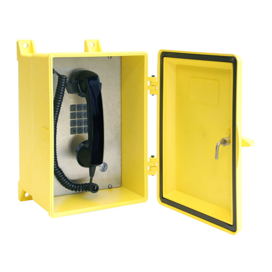
Pub. 42004-547A NEMA 4X VoIP Telephones Page 3 of 17 Hardware Description External NEMA 4X VoIP telephones may contain a handset, standard keypad, volume control push button, and ringer. The handset rests on a cradle that has a magnetic reed switch to signal an off-hook condition (see Figure 2). -
Page 6: System Requirements And Limitations
Pub. 42004-547A NEMA 4X VoIP Telephones Page 4 of 17 System Requirements and Limitations These VoIP telephones require PoE (Power-over-Ethernet) or a local 24 to 48-volt dc power source for operation. Two VoIP telephones can communicate in a peer-to-peer configuration without the need for a LAN. -
Page 7: Installation
Pub. 42004-547A NEMA 4X VoIP Telephones Page 5 of 17 Installation Safety Guidelines ATTENTION —Installation must be performed by qualified personnel and only in accordance with the National Electrical Code or applicable local codes. Please adhere to the following guidelines to ensure the safety of all personnel when installing GAI- Tronics telephone equipment: •... -
Page 8: Security Hardware
Pub. 42004-547A NEMA 4X VoIP Telephones Page 6 of 17 Security Hardware Model 354-71x Series Telephones are vandal-resistant; the front panel is attached to the enclosure with security screws. A GAI-Tronics Model 233-001 Security Screwdriver (sold separately) or Torx T-25 security head tip (included with the telephone) is required to install the security screws. - Page 9 Pub. 42004-547A NEMA 4X VoIP Telephones Page 7 of 17 Figure 4. Mounting and Conduit Entry Locations P:\Standard IOMs - Current Release\42004 Instr. Manuals\42004-547A.docx 03/20...
-
Page 10: Open The Telephone
Pub. 42004-547A NEMA 4X VoIP Telephones Page 8 of 17 Open the Telephone 1. Remove the four screws from the front panel and turn it to the right so that the interior surface faces out (see Figure 5). Keep all wiring connected. 2. -
Page 11: Recommended Cable
Pub. 42004-547A NEMA 4X VoIP Telephones Page 9 of 17 Recommended Cable Table 2. Recommended Cable Cable Use Size Cat5 or Cat5e UTP cable with an RJ-45 connector Power Two-conductor, No. 18 AWG is typical Inputs Two-conductor, No. 22 AWG is typical Output contacts Two-conductor, No. -
Page 12: Auxiliary I/O
Pub. 42004-547A NEMA 4X VoIP Telephones Page 10 of 17 Figure 6. Internal PCBA Connections Auxiliary I/O Inputs The telephones have four auxiliary inputs for customer use. Terminate these inputs to terminal block P12, on the VoIP Carrier PCBA (see Figure 6). Connect each input between the desired input (INPUT 1–4) and common (GND) on terminal block P12. -
Page 13: Usb Port
Pub. 42004-547A NEMA 4X VoIP Telephones Page 11 of 17 Outputs The telephones have two dry-contact outputs for customer use. Terminate these outputs to connector P2 on the relay PCBA (see Figure 6). Table 5. Output Contacts—Connector P2 Label Description Common Output 2 Normally Open Output 2 Common Output 1... -
Page 14: Voip Telephone Initial Network Configuration
Pub. 42004-547A NEMA 4X VoIP Telephones Page 12 of 17 VoIP Telephone Initial Network Configuration Configure each VoIP PCBA for operation on the network prior to installation. Assign a local ID, domain, proxy, and registrar. 1. Assign a host name. Host names provide identification of different VoIP PCBAs on the network. -
Page 15: Maximum (Handset Receiver) Level Remote Control
Pub. 42004-547A NEMA 4X VoIP Telephones Page 13 of 17 The duration of activation, or on/off times, can also be set in some modes. Refer to Pub. 42004-548, for programming instructions for the outputs (see the Reference Documentation section). Maximum (Handset Receiver) Level Remote Control The receiver volume level can be controlled remotely by changing the setting in the configuration file. -
Page 16: Troubleshooting
Pub. 42004-547A NEMA 4X VoIP Telephones Page 14 of 17 Troubleshooting Table 6. Troubleshooting Chart Problem Possible Solution Low volume in handset Increase the volume setting using the Volume Adjust button on the front or headset panel. High volume in handset Decrease the volume setting using the Volume Adjust button on the front or headset panel. -
Page 17: Voip Circuit Pcba Pushbuttons
Pub. 42004-547A NEMA 4X VoIP Telephones Page 15 of 17 VoIP Circuit PCBA Pushbuttons Reset Press the RESET button momentarily to warm reboot the telephone (see Figure 7). The telephone maintains the current configuration. Figure 7. VoIP PCBA Indicators and Buttons Factory Use the FACTORY button (see Figure 7) to erase the current configuration and restore the factory default settings as follows:... -
Page 18: Replacement Parts And Accessories
Pub. 42004-547A NEMA 4X VoIP Telephones Page 16 of 17 Replacement Parts and Accessories Table 7. Available Parts and Accessories Part Number Description 10113-122 Replacement Handset Assembly, 6-Foot Hytrel Cord 12505-005 Replacement Door Assembly, Gray 12505-005OR Replacement Door Assembly, Orange 12505-005RD Replacement Door Assembly, Red 12505-005YL... -
Page 19: Environmental
Pub. 42004-547A NEMA 4X VoIP Telephones Page 17 of 17 THD @ 1 kHz ........................... 1% minimum Inputs Keypad* ............................3 × 4 matrix Push buttons ..........................volume control Configurable inputs (quantity = 4) .............. internal pull-up 3.3 V dc tolerant *Not available on all models. - Page 20 Warranty Equipment. GAI-Tronics warrants for a period of one (1) year from the date of shipment, that any GAI-Tronics equipment supplied hereunder shall be free of defects in material and workmanship, shall comply with the then-current product specifications and product literature, and if applicable, shall be fit for the purpose specified in the agreed upon quotation or proposal document.
Need help?
Do you have a question about the GAI-TRONICS NEMA 4X 354-710 and is the answer not in the manual?
Questions and answers