Sign In
Upload
Download
Add to my manuals
Delete from my manuals
Share
URL of this page:
HTML Link:
Bookmark this page
Add
Manual will be automatically added to "My Manuals"
Print this page
×
Bookmark added
×
Added to my manuals
Manuals
Brands
Daikin Manuals
Air Conditioner
RNE50LV1
Service manual
Daikin RNE50LV1 Service Manual
Hide thumbs
1
2
Table Of Contents
3
4
5
6
7
8
9
10
11
12
13
14
15
16
17
page
of
17
Go
/
17
Contents
Table of Contents
Bookmarks
Advertisement
Quick Links
1
Table of Contents
2
Outer Panels
3
Outdoor Fan / Fan Motor
4
Electrical Component Assy
5
Compressor
Download this manual
Si011415E
REMOVAL
PROCEDURE
S E R V I C E
M A N U A L
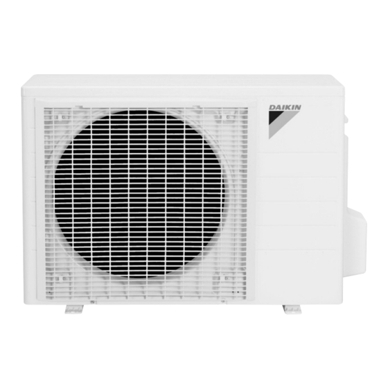
5.0 kW Class
Outdoor Unit
Non-Inverter
Pair Type
Table of
Contents
Previous
Page
Next
Page
1
2
3
4
5
Advertisement
Need help?
Do you have a question about the RNE50LV1 and is the answer not in the manual?
Ask a question
Questions and answers
Related Manuals for Daikin RNE50LV1
Air Conditioner Daikin FTKS20CVMB(9) Service Manual
Inverter pair wall mounted type c-series d-series (248 pages)
Air Conditioner Daikin FTKS20CVMB Service Manual
Inverter pair wall mounted type (246 pages)
Air Conditioner Daikin AT12BV1LS Pocket Manual
Service diagnosis split & multi (169 pages)
Air Conditioner Daikin RXS50J2V1B Installation Manual
(15 pages)
Air Conditioner Daikin RXS71E3V1B Installation Manual
(14 pages)
Air Conditioner Daikin FT10LV1L Technical Manual
Wall mounted l/m/p/311 series (61 pages)
Air Conditioner Daikin F Series Technical Manual
Split unit air conditioner ceiling cassette cooling only 50hz (51 pages)
Air Conditioner Daikin FCRN50EXV1 Installation Manual
Ceiling cassette r410a split type air conditioner e series (27 pages)
Air Conditioner Daikin PCRHK1015 User Manual
Slit type air conditioner (6 pages)
Air Conditioner Daikin RNE50MV1 Service Manual
(17 pages)
Air Conditioner Daikin FTNV20JVAK Installation Manual
(52 pages)
Air Conditioner Daikin RNE35LV1 Service Manual
(17 pages)
Air Conditioner Daikin RNE35MV1V9 Service Manual
(17 pages)
Air Conditioner Daikin RE24MV2S Removal Procedure
(21 pages)
Air Conditioner Daikin RN25HV1A Service Manual
(25 pages)
Air Conditioner Daikin H Series Technical Manual
Split systems air conditioner ducted blower (80 pages)
This manual is also suitable for:
Rne50mv1
Rne50mv14
Rne50mv1v
Print
Rename the bookmark
Delete bookmark?
Delete from my manuals?
Login
Sign In
OR
Sign in with Facebook
Sign in with Google
Upload manual
Upload from disk
Upload from URL


Need help?
Do you have a question about the RNE50LV1 and is the answer not in the manual?
Questions and answers