Advertisement
Quick Links
MCW-570
Automatic Flood Prevention System
1. INTRODUCTION
1.1 Purpose and Use
The MCW-570 is a fully supervised flood prevention system. It is triggered
by up to 10 flood detectors that are located inside the protected site
where presence of water flooding or leakage is probable.
Upon cold/hot water flood detection, the system automatically shuts off
the water supply to the protected site (by means of 1 or 2 cold/hot electro-
mechanical ball valves) and provides valve status indication, on the
Control Unit and on the water valve(s).
Turning ON the water supply, after repairing the water leak, is performed
by pressing the OPEN button - see figure 1.
Manual turning OFF the electro-mechanical ball valve is also possible, by
pressing the CLOSE button - see figure 1.
In case of power failure, it is possible, on some models, to manually
open/close the valve (see Fig. 8).
Optional - In addition to flood preventing, the system can also send ALARM,
TROUBLE and LOW BATTERY signals to a remote control unit for remote
indication (see figure 7).
Up to 10 detectors
MCT-550
Flood detector
CONTROL UNIT
Close
Open
Flood
button
button
Sensor
WATER
Flood
Sensor
MCT-550
Flood detector
(see spec.)
WATER
Figure 1 - Typical System Application
2. SPECIFICATIONS
2.1 Control Unit Specifications
RF SECTION
Front-End Module: Super-regenerative UHF receiver.
Operating Frequency (MHz): 315, 433, 868.95 or other frequency
according to local requirements in country of use .
DATA PROCESSING SECTION
ID codes: Over 16,000,000 possible 24-bit combinations
Total Message Length: 36 bits
ID Learning Capacity: Up to 10 different ID codes
ELECTRICAL DATA
Input Voltage (according to the electronic module type and cold water
valve diameter):
Electronic Module Cat. #
Cold water
E-200856
3/4' or 1"
E-202355
1-1/4"
Current
Drain
@9VAC:
Standby
closing/opening process only - up to 200 mA.
Relay Outputs: Form 1C (N.C. and N.O.)
Relay Contact Ratings: 1A resistive, 30 VDC or AC.
Status Outputs: 2, up to 100 mA each, open-collector type
ELECTRO-MECHANICAL BALL VALVE
Max water pressure: 8 Bar
Valve Diameter for Hot Water: 1/2"
Valve Diameter for Cold Water: 3/4", 1" or 1-1/4".
Valve closing Time: 5-11 seconds
PHYSICAL
Operating Temperatures: 0˚C to 49˚C (32˚F to 120˚F)
Control Unit Dimensions (HxWxD): 108x165x38 mm (4-1/4x6-1/2x1-1/2").
D-300767
1 or 2 cold/hot
Electro-mechanical
READY LED
(green)
ball valves
CLOSED LED
(red)
Alarm, trouble and
low battery signals
to a remote
control panel
(option)
Valve diameter
Input Voltage
Hot water
1/2"
9V / 0.35A Min.
-
12VAC / 1A Min.
-
30
mA.
During
2
1.2 Kit Contents
The MCW-570 system includes the following (see figure 1):
a. One Control Unit: In case of flood, the Control Unit receives signal
from up to 10 wireless water flood detectors, sends OFF command to
the water electro-mechanical valve(s) and provides indication of the
closed valve(s).
b. One wireless flood detector MCT-550: The flood detector transmits
an alarm signal to the Control Unit upon flood detection.
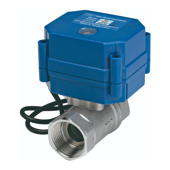
c. One cold water electro-mechanical ball valve: The electro-
mechanical ball valve is directly installed on pipe of central water
supply. The valve automatically turns OFF the water supply in case of
flood detection.
d. One power transformer - 9VAC output.
Note: The system is designed for use with water valves that are supplied
by the system manufacturer only.
1.3 LEDs Operation
The Control Unit includes 2 main LED indicators (see Fig. 1), that function
according to the following table:
Valve Status
Power-up
Opened (no flood)
Closed
During opening / closing
Opened manually (override) by
user although flood still exists
The Control Unit includes 2 additional LED indicators (in the receiver module -
see Fig. 6), that are visible only after removal of the Control Unit cover:
• Red SIGNAL / MEMORY STATUS LED - illuminates as long as the
receiver receives signal from recognized flood detector. This LED is
also used during the flood detectors "learning" process (described
in par. 3.3).
• Yellow MEMORY LOCATION STATUS LED indicator - used during
the "learning" process.
Weight: Control Unit - 217 g (7.6 oz.), 3/4" WATER VALVE - 345g (12
oz.), 1" WATER VALVE - 526g (18 oz.), 1-1/4" WATER VALVE 1.6Kg
(3-1/2 Lb), AC ADAPTER - 200g (7 oz.).
Control Unit Color: Off white
COMPLIANCE WITH STANDARDS
EN13564-1, EN13564-2, EN60950, EN300220, EN301489
2.2 Flood Detector MCT-550 Specifications
TRANSMITTER
Frequency (MHz): 315, 433, 868.95 or other frequency according to local
requirements in country of use
Transmitter's ID Code: 24-bit digital word, over 16 million combinations,
pulse width modulation.
Overall Message Length: 36 bits
Message Repetition: One-shot transmission (default) or once every 3
minutes (selectable).
Supervision: Signaling at 60-minute intervals (U.S. version) or 15 minute
interval (UK version), or according to the local standards.
valves
Response to Tamper Event: Tamper report every 3 minutes (until the
tamper switch is restored).
ELECTRICAL DATA
Power Source: 3V Lithium battery, Panasonic type CR-2 or equivalent.
Note: Dispose of used battery according the manufacturer's instructions.
Nominal Battery Capacity: 750 mAh
Current Drain: 6µA STBY, 17mA average in operation (including LED).
Battery Life with LED on: 3 years (for typical use)
Battery Supervision: Automatic reporting of battery condition data as
part of any transmission.
ALARM REPORT:
Every 20 sec. for the first 3 minutes. Every 3 min. for the next 27 minutes.
Alarm stops reporting after 30 min., or if the detector goes into "alarm restore".
Length of Flood Sensor Cable: 3 meters (10 ft)
Installation Instructions
Red LED
High frequency
flashing
Does not light
Lights
High frequency
flashing
Low frequency
flashing
Green LED
High frequency
flashing
Lights
Lights
Lights
Lights
1
Advertisement

Related Manuals for Visonic MCW-570


Summary of Contents for Visonic MCW-570
- Page 1 1.1 Purpose and Use 1.2 Kit Contents The MCW-570 is a fully supervised flood prevention system. It is triggered The MCW-570 system includes the following (see figure 1): by up to 10 flood detectors that are located inside the protected site a.
- Page 2 PHYSICAL DATA This device complies with Part 15 of the FCC Rules and RSS 210 of Industry and Science Canada. Operation is subject to the following two conditions: (1) Weight of Flood Sensor Cable: Approx. 60 gr. This device may not cause harmful interference, and (2) this device must accept Operating Temperature: 0°C to 49°C (32°F to 120°F).
- Page 3 SENSOR (recommended by the manufacturer). CABLE length) SW3: If the detector will be used only with MCW-570, the position FLOOD of this switch is not important. If the detector will be used with Press the flexible SENSOR other systems (e.g. PowerMax), this switch enables (ON) or...
- Page 4 Directive 2002/96/EC Waste Electrical and Electronic Equipment. VISONIC LTD. (ISRAEL): P.O.B 22020 TEL-AVIV 61220 ISRAEL. PHONE: (972-3) 645-6789, FAX: (972-3) 645-6788 VISONIC INC. (U.S.A.): 65 WEST DUDLEY TOWN ROAD, BLOOMFIELD CT. 06002-1376. PHONE: (860) 243-0833, (800) 223-0020. FAX: (860) 242-8094 VISONIC LTD. (UK): 7 COPPERHOUSE COURT, CALDECOTTE, MILTON KEYNES.
Need help?
Do you have a question about the MCW-570 and is the answer not in the manual?
Questions and answers