Table of Contents
Advertisement
Quick Links
MCT-442
Supervised Indoor Wireless CO Gas Detector
1. INTRODUCTION
The carbon monoxide (CO) detector is designed to monitor the
CO gas level in residential dwellings and give early warning
before potentially dangerous levels exist. The CO alarm is
transmitted to the PowerMax+ (version F and up) or PowerMax
Pro and presented on its display.
The CO gas is considered to be a highly dangerous poisonous
gas because it is colorless, odorless, tasteless and very toxic.
Presence of CO gas inhibits the blood's capacity to transport
oxygen throughout the body, which can eventually lead to brain
damage. CO gas is produced by incomplete combustion of fuels
(such as natural gas, propane, heating oil, kerosene, coal,
charcoal, gasoline or wood) that can occur in any device that
depends on burning for energy and heat (such as furnaces,
boilers, room heaters, hot water heaters, stoves, grills and in any
gasoline powered vehicle or engine).
Before CO harmful level is reached, the detector's internal buzzer
beeps sound periodically and the detector's red LED flashes. In
this condition, the buzzer sound can be stopped for 6 minutes by
pressing the TEST/MUTE switch. It will not correct the CO gas
problem, but will temporarily silence the buzzer while you correct
the problem. After 6 minutes, the detector restarts alarm if the CO
level remains high.
2. SPECIFICATIONS
CO DETECTION
Detection principle: Electrochemical cell
Detector Active Life: 5 years
Selectable Sensitivity:
DIP switch in EN Mode
No warning at 30 ppm for 120 minutes, 50 ppm for 60 minutes,
100 ppm for 10 minutes.
Warning at 50 ppm between 60-90 minutes, 100 ppm for 10-40
minutes, 150 ppm within 3 minutes.
DIP switch in UL Mode
No warning at 30 ppm for 30 days, 70 ppm for 60 minutes, 150
ppm for 10 minutes, 400 ppm for 4 minutes.
Warning at 70 ppm between 60-240 minutes, 150 ppm for 10-
50 minutes, 400 ppm between 4-15 minutes.
Audible Alarm Volume: >85db at a distance of 3m (10 ft.).
TRANSMITTER AND CODING
Operating Frequency (MHz): USA/UL - 315, 433, 868.95,
869.2125 or other frequency according to local requirements.
Transmitter's ID Code: 24-bit digital word, over 16 million
combinations, pulse width modulation. PowerCode or Zigbee
Protocols.
Overall Message Length: 36 bits
Supervision: Automatic signaling at 60-minute intervals (315
MHz version), 15-minute interval (433.92, 868.95, 869.2125 MHz
versions) or according to the local standards.
Transmitted Messages: CO gas alarm, low battery, tamper,
sensor end of life, sensor trouble, supervision.
Tamper Alerts: Tamper message is transmitted to the
PowerMax+ / PowerMax Pro control panel when the detector is
removed from its bracket.
ELECTRICAL DATA
Power Source: 9 volt Lithium battery (Ultra Life #U9VL, U9VL-J),
or Alkaline battery, Energizer #522.
Current Drain: For UL: 25 µA standby, 15mA in alarm
For other models: 11 µA standby, 250µA in alarm
Battery Life Expectancy: At least 1 year (for typical use)
Battery Supervision: Automatic transmission of battery status
data as part of any transmitted message.
D-300273
Installation Instructions
The detector provides
low battery and detector
end-of-life indications.
Caution: The detector
expiry date is stamped
on the detector. After
the expiry date, the
detector should not be
used - do not wait for
end-of-life indication!!
The detector is continuously self-tested and has a TEST button
that enables the user to test the detector anytime.
Note: The TEST/MUTE switch functions as TEST switch (in
normal operation) or as MUTE switch (in alarm condition).
The tamper switch actuator (fig. 3), is pressed against the bracket
when the unit is attached to the bracket. Removal of the unit from
the bracket causes the switch contacts to open, creating a tamper
event, which is reported by the transmitter to the alarm system
control panel.
Visual and Audible Indications:
Visual Indication (LEDs)
Condition
Red
Yellow
Alarm
4 flashes
-
(*)
End of Life
-
3
/ Fault
flashes
every
60 sec.
Battery OK
-
-
Low
-
1 flash
battery
every
60 sec.
MUTE
4 flashes
-
button is
(*)
pressed (to
silent the
alarm for 6
minutes)
TEST
1 flash
1 flash
button is
(the 1st
(the 2nd
pressed
LED)
LED)
* Every 5 seconds during the first 4 minutes, every 60 sec. after
the first 4 minutes.
** After 6 minutes, the detector restarts alarm if the CO level
remains high.
Note: Long period of low battery condition may cause improper
function. In case of End-of-Life/Fault indication, replace the
battery and check if the End-of-Life/Fault indication still exists. If it
still exists, stop using the detector.
PHYSICAL DATA
Operating Temperature: 0°C to 40°C (32°F to 104°F).
Relative Humidity: 10-93% ± 2% RH
Dimensions: 127 mm (5 in.) x 40 mm (1-9/16 in.)
Weight (without battery): 180g (6.35 oz)
Compliance with Standard:
Europe: EN50291, EN 50130-4, EN 300220, EN 301489.
Certified by LPCB (UK)
USA (315MHz): UL2075, CFR47 part 15.
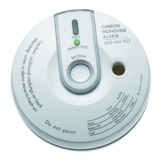
ALARM
(red) LED
Battery
(green) /
Fault
(yellow)
LED
TEST /
MUTE
BUTTON
Figure 1 - General View
Audio
Indication
Green
-
4 beeps (*)
-
one beep
every 60 sec.
Flashes once
-
every minute
-
one beep
every 60 sec.
-
OFF for 6
minutes (**)
Flashes (the
1 beep
3rd LED) If
CO circuit test
and battery
are OK - lights
during 2 sec.
1
Advertisement
Table of Contents

Related Manuals for Visonic MCT-442


Summary of Contents for Visonic MCT-442
-
Page 1: Installation Instructions
MCT-442 Installation Instructions Supervised Indoor Wireless CO Gas Detector 1. INTRODUCTION The carbon monoxide (CO) detector is designed to monitor the The detector provides ALARM CO gas level in residential dwellings and give early warning (red) LED low battery and detector before potentially dangerous levels exist. - Page 2 3. PREPARATIONS 3.1 Disassembly Open battery cover and connect the battery to its 9 volts terminals (without insulator). BRACKET Veri fy pr op er pol arity. Red button DETECTOR Tab (1 of 4) Hold the Battery cover bracket with one hand Function selector: Rotate the Sw.
- Page 3 A-2. Where Not to Install CO Detectors 5. In locations where furniture or draperies may obstruct the air flow. 6. In exhaust streams from gas engines, vents, flues or 1. In location where temperature may be below -10°C (14°F) or chimneys.
- Page 4 CO problem. Warning! Changes or modifications to this equipment not expressly approved by Visonic Ltd. could void the user’s authority to operate the equipment. The 315 MHz version of this device complies with Part 15 of the FCC Rules. Operation is subject to the following two conditions: (1) This device may not cause harmful interference, and (2) This device must accept any interference received, including interference that may cause undesired operation.
Need help?
Do you have a question about the MCT-442 and is the answer not in the manual?
Questions and answers