Table of Contents
Advertisement
Quick Links
Advertisement
Table of Contents

Related Manuals for Scarlet Tech WR-3 Plus


Summary of Contents for Scarlet Tech WR-3 Plus
- Page 1 WR-3 Plus Wireless Anemometer User Guide...
-
Page 2: Table Of Contents
Page Contents Introduction Sensor & Receiver Sensor Wireless Connection Transmission Range Receiver Keypad Navigation Diagram MAIN page AVG/MAX page CHART page HISTORY page SETTINGS Page WIND SPEED settings page DATA LOGGING settings page GENERAL settings page Functions Sensors Pairing Wind Speed Alarm Data Logging Data Export Power Saving Mode... -
Page 3: Introduction
Users can receive instant data and wind speed alarm at a distance up to 500-meter radius from the sensor. WR-3 Plus further supports data logging and can export data in excel format to computers by using micro USB output. -
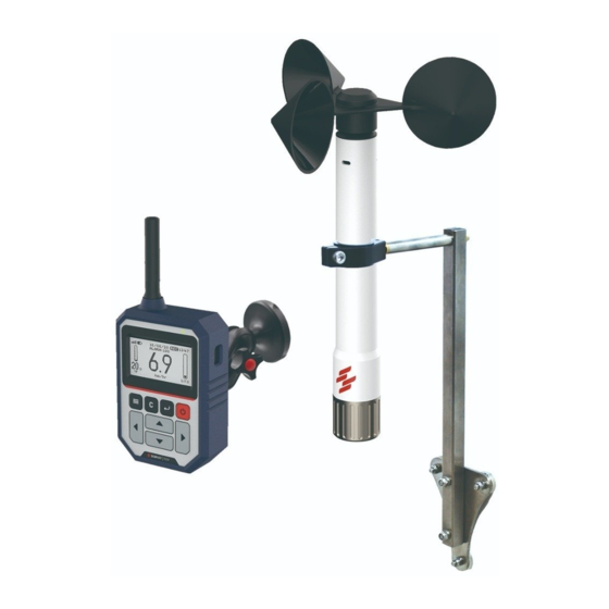
Page 4: Sensor & Receiver
Sensor & Receiver Sensor Wind Cups Wind Speed Sensor Temperature & Atmospheric Pressure Sensor Sensor Body Weighted Bottom Cap (1/4” Threaded Hole) Wireless Connection Each sensor has a unique wireless address number that has been pre-paired corresponding to the receiver display. One sensor can be connected to multiple receivers. Several anemometers can operate in close proximity without disturbance. -
Page 5: Receiver
Receiver Antenna LED Indicator Micro USB Port Display Slip-proof Holster Keypad Battery Cover... -
Page 6: Keypad
Keypad Settings Power Cancel Enter Left Right Down icon Name Functions Power Power ON / OFF Settings Go to Main / Settings page Enter Select; Confirm Cancel Cancel; Go back to the previous page Up; Increase number; Change option Down Down;... -
Page 7: Navigation Diagram
Navigation Diagram After pressing the Power button, the receiver will enter the MAIN page. Users can press Right/Left and Settings /Cancel buttons to navigate through the pages. : Switching by Right and Left buttons : Switching by Settings and Cancel buttons : Switching by Enter and Cancel buttons MAIN AVG / MAX... -
Page 8: Main Page
MAIN page Number Name Definition Signal Strength The wireless signal strength between sensor and receiver Receiver Power Receiver battery level or power supply through micro USB Wind Alarm Threshold The set wind speed alarm trigger threshold Date Current date in DD/MM/YY Data Logging Indicate the data logging function is turn ON Time... -
Page 9: Avg/Max Page
AVG/MAX page Item Name Definition Maximum Wind Speed Maximum wind speed for the past 12 hours since Receiver turns ON Average Wind Speed Average wind speed for the past 12 hours since Receiver turns ON Wind Chill Current wind chill index Atmospheric Pressure Current atmospheric pressure CHART page... -
Page 10: History Page
HISTORY page Item Name Definition Time Period The past 12 hours of wind data from the current time (from -1 to -12) Average Wind Speed Average wind speed of the corresponding period Maximum Wind Speed Maximum wind speed of the corresponding period Average Temperature Average temperature of the corresponding period... -
Page 11: Settings Page
SETTINGS Page Item Name Definition Wind speed page Wind speed and alarm setting Data logging page Data logging setting and management General page General setting page Version Current receiver firmware version info WIND SPEED settings page Item Name Definition Wind Speed Unit Wind speed measurement unit: m/s (default), km/hr, MPH, knots Alarm... -
Page 12: Data Logging Settings Page
DATA LOGGING settings page Item Name Definition Logging Logging function: ON / OFF(default) Logging interval Data logging interval: 2 sec, 5 sec, 10 sec (default), 1 sec, 5 min, 10 min, 60 min Clear data Clear all data to release the memory Available memory Remaining data storage space in percentage... -
Page 13: General Settings Page
GENERAL settings page Item Name Definition Date Set current data. DD/MM/YY Time Set current time. HH:MM (24hr military time) Sensor Address Set the wireless sensor address number that connected to this receiver Temperature unit Unit for temperature measurement. °C (default)/°F Atmospheric pressure unit Unit for atmospheric pressure measurement. -
Page 14: Functions
Functions Sensors Pairing The wireless address number is labelled on the sensor body, as well as in the setting of each receiver. WR-3 PLUS WIND SENSOR AD:23 SN:2001AT0023 PN:STAWR2T01 OPEN FOR BATTERY REPLACEMENT (ER18505 3.6V LITHIUM) Change Receiver wireless address: 1. -
Page 15: Wind Speed Alarm
Wind Speed Alarm The built-in buzzer will be triggered when the wind speed exceeds the set threshold. The display backlight flashes AMBER and LED indicator continuously lights up in RED. Set alarm threshold: 1. press Settings button go to SETTINGS page 2. -
Page 16: Data Export
Data Export 1. Download and unzip “WR3PR.zip” file to your PC from Scarlet’s website: https://scarlet-tech.com/wp-content/uploads/2021/02/WR3PR.zip 2. Connect the receiver to PC via micro USB cable. Make sure the datalogging feature is turn OFF (see Finish Logging) A new USB drive will show up on your devices list indicates the receiver is connected to your computer. 3. - Page 17 8. Wait for the “Finish” pop-up that indicates the data exporting is complete. Depending on the data amount and PC performance, the downloading time will vary from a few minutes up to half an hour. *Please update the USB driver if the COM port is unidentified. 1.
-
Page 18: Power Saving Mode
Power Saving Mode In power saving mode, the LED indicator will light GREEN every 10 seconds. While the wind speed alarm function is ON, the buzzer will be triggered while wind speed exceeds the set threshold. Enable power saving mode: 1. -
Page 19: Installation
CLICK Receiver Installation WR-3 Plus’s Receiver Holder Kit comes with an anti-slip display holder with neodymium magnets on both ends and three pieces of adhesive metal flakes. 1. Peel off the backing paper of the metal flake to reveal the adhesive side 2. -
Page 20: Technical Specification
Technical Specification Wireless Sensor Item Definition Frequency 868MHz, 915MHz Distance Max 500m* (depends on the applied environment) Data Rate Every 2 seconds Power Supply 3.6V 18505 Lithium battery x1 Waterproof Rating IP67 Weight 360g Dimension 262.5 x 183.5 x32mm Receiver Item Definition Receiver Buzzer... -
Page 21: Wind Speed Sensor
Wind Speed Sensor Item Definition Measurement Unit m/s (default) knots km/hr Measurement Range 0.3…50 m/s Measurement Resolution 0.1 m/s 0.1 knots 0.1 MPH 0.1 km/hr Measurement Accuracy ±2% FS Temperature Sensor Item Definition Measurement Unit ℃ (default) ℉ Measurement Range -30℃…60℃... -
Page 22: Packing Content
▪ 3.6V 18505 Lithium battery x1 (placed in Sensor) ▪ User Manual & Certificate Wireless Wind Cups Receiver Receiver Receiver Sensor Antenna Holder WR-3 Plus Wireless Anemometer User Guide AA Battery x 3 3.6V 18505 User Manual & Certificate (for Receiver) Lithium battery x1 (placed in Sensor) - Page 23 Optional Accessories ▪Magnetic Sensor Mounting Bracket ▪Spare Wind Cups ▪Spare Sensor Battery (3.6V 18505 Lithium battery) ▪External Antenna Magnetic Sensor Wind Cups 3.6V 18505 Lithium battery x1 Mounting Bracket (placed in Sensor)
-
Page 24: Safety, Maintenance, & Warranty
Safety, Maintenance, & Warranty Operating Environment The operating temperature of the anemometer system is designed to work in an ambient tempera- ture between 5°C to 60°C (40°F to 140°F) at 20~80%RH. The storage temperature is between -20°C to 60°C (-4°F to 140°F). The instrument can be damaged if stored and operated outside of these temperature ranges. - Page 25 ▪Make sure the O-ring is correctly aligned to the battery cap for waterproof protection. ▪Put back the battery cap in clockwise direction to finish the battery changing. O-ring Receiver Battery Replacement The receiver is powered by 3 AA 1.5V batteries. The battery level is displayed on the top of the display. ▪Remove the screw and then remove the battery cover on the back.
- Page 26 Warranty Conditions This instrument is guaranteed for a one-year limited warranty against material or production defects, in accordance with our general sales conditions. During the warranty period, Scarlet Tech reserves the right to decide either to repair or replace the product.
- Page 27 Scarlet Tech Co., Ltd. © 2021 Scarlet Tech Co., Ltd. All rights reserved. 4F-3, No. 347 , HePing E Rd, 2nd Sec, DaAn District, Taipei City 106, Taiwan info@scarlet.com.tw www.scarlet-tech.com version 210311...
Need help?
Do you have a question about the WR-3 Plus and is the answer not in the manual?
Questions and answers