Table of Contents
Advertisement
Quick Links
Advertisement
Table of Contents

Related Manuals for Scarlet Tech ST-11D


Summary of Contents for Scarlet Tech ST-11D
- Page 1 ST-11D Sound Level Meter User Guide...
- Page 2 Precaution *Please read the manual carefully before using the meter. *Do not touch any parts of the unit only if necessary for operation. *Do not disassemble or modify the unit. *In case of malfunction, do not attempt to do any repairs. *The warranty doesn’t apply to damage on the meter diaphragm and other improper use.
-
Page 3: Table Of Contents
Contents 1. General Introduction 2. Specification 3. Structure features and function 4. Operation before measurement 4.1 Check list 4.2 Use of windscreen 4.3 External power supply 4.4 Check and change of battery 5. Calibration 5.1 Acoustic calibration 5.2 Calibration setup 5.3 Calibration history list 6. -
Page 4: General Introduction
General Introduction Model ST-11D Sound level meter is a digital and multifunction sound level meter with modular design. Its measurement solution is in accordance with IEC 61672: 2013 Class 1 standard and its sensitivity for emission in radio frequency filed is classified as group X. -
Page 5: Specification
Specification (1) Microphone: Φ12.7mm (1/2'') pre-polarization condenser microphone. Sensitivity: 30mV/Pa. See the Appendix A. ST-11/11D can also be equipped with other types of microphones to measure noise which is very low or very high. Types of microphones External Sensitivity Frequency Type diameter mV/Pa) - Page 6 8dB. (17) Main Parameters of Measurement ST-11D: LFp, LSp, LIp, Leq,t, Lpeak, Leq,T, LFmax, LFmin, LSmax, LSmin, LImax, LImin, SEL, Lex8h, LAVG, TWA, DOSE, Ln1, Ln2, Ln3, Ln4, Ln5, SD,Ts, Tm, Volt, E. Note: the n1 to n5 in Ln1-Ln5 can be chosen from 1 to 99.
-
Page 7: Structure Features And Function
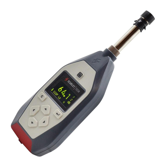
Structure features and function The outline of the Sound Level Meter is shown in figure 1. It consists of microphone, preamplifier and the main unit. During normal operation, the measuring microphone and the preamplifier are installed on the head of the main unit, connected with the main unit through knurled nut. - Page 8 Fig 3 Table 1 Keys function Table 1 Keys function Power Power on or reset the meter on/reset Enter Enter the next menu or Input the current operation Exit Exit from the current menu or keep pressing for 3s to power off the meter Right Move cursor to next position cursor...
- Page 9 AC/DC output socket, the socket is stereo output socket, when matches with the plug, the definition of each pin plug shown as below: Fig 5. AC and DC output RS232 output socket, the socket type uses the RJ45 socket, pins are defined as below: RS232 port serial input, only two serial output signals, the pins are defined as follow: Power Empty...
-
Page 10: Operation Before Measurement
Table 2 Definition of symbol Definition Symbol Battery level display Microphone setup: diffusion field type Integrating measurement and statistical analysis are in progress Integrating measurement and statistical analysis are paused logging the varying waves of SPL with time Recording The measured signal surpasses the upper limit of measurement range The measured signal under the lower limit of measurement range... -
Page 11: Check And Change Of Battery
4.4 Check and change of battery There are two kinds of battery: 4×LR03 batteries or Lithium batteries. While operating, the meter will check battery power automatically, if it is low, the under-volt- age indicator will be lighted up, which reminds users to change batteries. -
Page 12: Acoustic Calibration
First row: Acoustic Calibration. You can use acoustic calibrator to calibrate the sensitiv- ity of the instrument. Second row: Calibration Setup. You can set the SPL of the acoustic calibrator or the sensitivity of the microphone. Third row: Calibration History of the instrument. 5.1 Acoustic calibration Move the cursor on the first row and press key, then you enter the calibration... -
Page 13: Calibration History List
It takes 10 seconds to do the calibration. Then turn the calibrator ST-120 to 114.0 dB. Press key to make it reach the output SPL of the calibrator. Repeat calibra- tion at the level of 114.0dB. 5.3 Calibration history list Move the cursor on the second row on calibration submenu, and press key to enter the calibration history list. -
Page 14: List Display Interface
L90, L95, SD, Ts, Tm, Volt, Date, Time, and E . The last row “LW” is the logging and sound recording function open. Note: the logging and sound recording function is the optional function in ST-11D. 6.4 “Setup1” submenu 6.4.1 Page 1 Move the cursor to “2.Setup1”... - Page 15 “Work Mode”: To meet different measurement standards and purposes, ST-11 has many parameters for you to choose. You can preset the parameters according to the relevant standards and purposes, divide them into different parameter combinations and make different names. Then you only need to choose the relevant parameter combinations for your measurement requests and do not need to set every parameter.
- Page 16 Cursor position Available options Remarks 3 or 1 Page turning 01h~24h hour 01m~59m minute 01s~59s second 5, 10, 50, 90 or 95 Numbers from 1 to 99 Set statistic sound level Sta. weighting F, S, I 6.4.3 Page 3 Move the cursor on “P:2” and press key when under “2.Setup1”...
-
Page 17: Setup2" Submenu
6.5 “2.Setup2” submenu Move the cursor on “4.Setup2” and press key when on the main menu, the instru- ment will enter page 1 under “4.Setup2” interface and display as follows: Fig 18. Page 1 of Step 2 “2.Setup2” is for setting of starting mode, auto-pause, restart, hardware, power supply, clock, logging and recording. - Page 18 Fig 22. Starting setup “Source”: trigger source, including Clock, Button, Equivalent interval, Limit-surpassing and serial. Applications of each trigger source are listed in the Table 3: Table 3 Applications of the trigger sources Source Remarks Clock Start when reach the specified time Button Start by pressing the Button Equivalent...
- Page 19 “Run Delay”: delay time for starting measurement can be set after pressing key. If 0s is chosen, is the measurement will start right away. Note:Though some certain trigger mode is chosen, you can still start measurement by pressing key while on “1.Meas”submenu interface. 6.5.1.3 Equivalent interval activation When choose “Equivalent interval”, the instrument displays as follows: Fig 25.
-
Page 20: Auto Pause/Restart Setup
“First Ts”: the measurement time for each group, the time can be set by user or choose between 1min, 5mim, 10min, 20min, 30min and 1hour. “Total”: the total groups of continuous measurement. The number can be set from 1 to 1440. -
Page 21: Calendar Clock Adjustment
6.5.3.1 Adjust the amplitude of AC output Move the cursor to “AC”, press key to set up the amplitude of AC output. There’re three gears can be set and each gear differs 10 times. “31mV/Pa” means when microphone gets 1 Pa sound pressure, the pins of AC output will output about 31mV AC signal. -
Page 22: Logging Setup (Optional)
2 under setup 2 interface. 6.5.5 Logging setup (Optional in ST-11D) Move the cursor to the third row when on page 3 under “setup 2” interface and press key, you can enter the recording setup interface. It displays as follows: Fig 32. -
Page 23: Data" Submenu
Table 6 Recording type Type Applications No recording 48kHz,16bit High sample frequency, high accuracy, big capacity files for further analysis. 16kHz,16bit Medium sample frequency, medium capacity files for further analysis. 8kHz, 8bit Low sample frequency, low capacity files only for monitoring “Vol”: Turn up the volume while recording. - Page 24 Fig 35. Data recall First row: the header; Last row: working status of the instrument, from left to right is”battery voltage, data recall, total groups of the data” Middle: the serial number and name of each group of data. The “>” on the far left is the cursor.
-
Page 25: Clear All
“1.Del.this file”: Press key when the cursor stays here, the instrument will delete the data group which is being viewed. “2.Display log”: Press key when the cursor stays here, the instantaneous SPL will be displayed. If the instantaneous SPL is not logged during integral measuring, “2.Dis- play log”... - Page 26 Fig 41 Basic information “Serial no.123456”: The meter serial number is 0123456. “Version:S_1.0/H_1.0”: The software version of the instrument is 1.0, the hardware version is 1.0. “Build: Sep 23 2011”: The software of the instrument was written on “Sep 11, 2011”. “File numbers:2”: 2 groups of data are stored in the instrument.
- Page 27 Appendix A: Nominal free field response of AWA14425 type test capacitor microphone in the reference direction Appendix B...
- Page 28 Appendix C The free field response of sound level meter in different directions under no wind condition and installed with φ35×60 windscreen...
- Page 29 Appendix D The frequency Response of free-field Type and Random Type microphone when directivity is 90 degrees in the free field...
-
Page 30: Appendix E: Vocabulary Of Terms
Appendix E: vocabulary of terms The instrument shows common symbols and terms Exchange When noise dose doubled, the added value of time weighting Rate average SPL Threshold If time weighted SPL less than the value, it will not participate in TWA, LAVG calculations Criterion When noise dose is more that this value, the corresponding instructor light will be lighted... -
Page 31: Warranty
Safety, Handling, & Maintenance Important safety information WARNING: Failure to follow these safety instructions could result in re, electric shock, or other injuries, or damage to sound level meter or other property. Read all the safety information below before using sound level meter. - Page 32 Scarlet Tech Co., Ltd. © 2015 Scarlet Tech Co., Ltd. All rights reserved. 4F-3, No. 347 , HePing E Rd, 2nd Sec, DaAn District, Taipei City 106, Taiwan info@scarlet.com.tw www.scarlet-tech.com version 200803...
Need help?
Do you have a question about the ST-11D and is the answer not in the manual?
Questions and answers