Advertisement
Quick Links
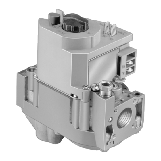
APPLICATION
The V8200 Continuous Pilot Combination Gas Controls are
used in gas-fired, standing pilot appliances. The include a
manual gas valve, safety shutoff, single automatic operator
and a pressure regulator.
FEATURES
• Add ECO switch where codes call for dual safety
shutoff.
• For use with 24 Vac heating appliances that burn
natural or liquefied petroleum (LP) gas.
• Capacity rated at 130 feet
3
drop (3.7m
/hr at 0.25 kPa). Maximum regulated
3
capacity is 200 feet
/hour (5.7 meter
regulated capacity is 20 feet
• Diaphragm-operated automatic valve opens under
control of the regulator and closes if gas or power
supply is interrupted.
• Three-position manual gas control knob has ON, OFF,
and PILOT positions.Separate reset button must be
held down to permit gas flow while lighting pilot; can
be pushed down only in PILOT positions. All
adjustments, wiring connections and pilot outlet are
accessible from the top of the gas control.
® U.S. Registered Trademark
Copyright © 2001 Honeywell • All Rights Reserved
Combination Gas Controls
3
/hour at 1 inch wc pressure
3
/hour). Minimum
3
3
/hour (.6 meter
/hour).
• Compact size.
• Straight-through body pattern right angle adapters
available for inlet and outlet.
• 1/2 inch inlet and 1/2 inch outlet; adapters available
for 3/8 or 3/4 inch inlet or outlet.
• Adjustable servo regulator effectively maintains
almost constant gas output pressure under wide
fluctuations in gas supply pressure. Factory setting
does not need readjustment for specific rating of
furnace.
• Inlet and outlet screens included.
• Pilot filter included.
• Wiring terminal block color-coded beige to identify
standing pilot models.
• May be installed at any angle between 0 and 90 degrees
from the upright position, including vertically.
• 1/4 inch quick-connect terminals for electrical
connections.
• 0°F to 175°F (-18°C to +79°C) temperature range
standard; -40°F to +175°F (-40°C to +79°C) available.
• Inlet and outlet pressure taps included; both taps
accessible from top of gas control.
• Standard, slow, and step-opening models available.
• ECO connector included with some models: also
available as accessory.
• Natural to LP gas conversion kit included with
standard and slow-opening models.
• LP to natural gas conversion kit available for standard
and slow-opening models.
Application .......................................................................
Features ...........................................................................
Specifications ...................................................................
Ordering Information ........................................................
Installation ........................................................................
Startup and Checkout ......................................................
Maintenance .................................................................... 11
Operation ......................................................................... 12
Service ............................................................................. 15
Instructions to the Homeowner ........................................ 15
V8200
PRODUCT DATA
Contents
1
1
2
2
4
9
68-0045- 3
Advertisement

Related Manuals for Honeywell V8200


Summary of Contents for Honeywell V8200
- Page 1 APPLICATION standing pilot models. • May be installed at any angle between 0 and 90 degrees The V8200 Continuous Pilot Combination Gas Controls are from the upright position, including vertically. used in gas-fired, standing pilot appliances. The include a • 1/4 inch quick-connect terminals for electrical manual gas valve, safety shutoff, single automatic operator connections.
- Page 2 V8200 Continuous Pilot Combination Gas Controls. For Type of Gas: use in standing pilot appliances. See Table 1 for model V8200 set up for natural gas includes a 393691 LP specifications. Models with a 7 following the suffix letter, Conversion Kit.
- Page 3 A right-angle flange cannot be used on the inlet end of the ECO Adapter is used. 4-1/8 (104) NOTE: Flange Kits include one flange with attached O-ring, (13) four mounting screws, 9/64 inch hex wrench and (25) M16284 instruction sheet. 2-11/16 (69) Fig. 1. V8200 dimensions in in. (mm). 68-0045—3...
- Page 4 To convert from natural gas to LP, use the 393691 LP Conversion Kit that is WARNING included with the V8200 gas control. To convert from LP to natural gas, use the 394588 Natural Gas Conversion Kit Fire or Explosion Hazard.
- Page 5 V8200 COMBINATION GAS CONTROLS by using an adapter. The adapter is installed on the end of the supply pipe in place of the gas control, following the same COLOR CODE FOR precautions and instructions that are used for installing the NATRUAL gas control.
- Page 6 V8200 COMBINATION GAS CONTROLS Install Gas Control TWO IMPERFECT 1. Mount the gas control 0-90 degrees, in any direction, THREADS GAS CONTROL from the upright position of the gas control knob, including vertically. 2. Mount the control so gas flow is in the direction of the PIPE arrow on the bottom of the gas control.
- Page 7 V8200 COMBINATION GAS CONTROLS WHEN FLANGE IS USED WHEN FLANGE IS NOT USED APPLY WRENCH APPLY WRENCH FROM TOP OR TO FLANGE ONLY BOTTOM OF GAS CONTROL TO EITHER SHADED AREA M3079 Fig. 7. Proper use of wrench on gas control.
- Page 8 V8200 COMBINATION GAS CONTROLS WIRING THERMOSTAT HIGH LIMIT CONTROLLER WARNING (HOT) Electrical Shock Hazard. OPTIONAL Can cause serious injury, death or equipment CONVENIENCE TH/TR damage. TERMINALS Disconnect power supply before making wiring connections to prevent electrical shock or equipment damage.
- Page 9 V8200 COMBINATION GAS CONTROLS STARTUP AND CHECKOUT Light the Pilot Burner Flame 1. Turn the gas control knob clockwise to OFF. Wait five minutes to dissipate any unburned gas. Sniff around WARNING the appliance near the floor. Do not relight the pilot flame if you smell gas.
- Page 10 V8200 COMBINATION GAS CONTROLS Check and Adjust Gas Input to Main Burner Standard-Opening and Slow-Opening Pressure Regulator 1. The gas control outlet pressure should match the CAUTION manifold pressure listed on the appliance nameplate. 2. With the main burner operating, check the gas control Equipment Damage Hazard.
- Page 11 V8200 COMBINATION GAS CONTROLS Table 7. Pressure Regulator Specification Pressures in Inches wc. Outlet Pressure Nominal Factory Setting Setting Range Nominal Inlet Model Type of Gas Pressure Range Step Full Rate Step Full Rate Standard, Slow- Natural 5.0 to 7.0 —...
- Page 12 The gas control allows pilot and main burner gas flow during the thermostat ON cycle, as shown in Fig. 13. When the The V8200 Gas Control provides 3-position (OFF-PILOT-ON) thermostat calls for heat, the magnetic valve operator is manual control of gas flow. The OFF position prevents pilot energized and lifts the automatic operator valve disc off its and main burners gas flow.
- Page 13 V8200 COMBINATION GAS CONTROLS GAS CONTROL KNOB AUTOMATIC VALVE OPERATOR AUTOMATIC OPERATOR RED RESET SOLENOID SERVO PRESSURE BUTTON REGULATOR AUTOMATIC OPERATOR VALVE DISC RESET BUTTON VALVE DISC PILOT OUTLET CONTROL INLET CONTROL OUTLET SAFETY SHUTOFF VALVE MANUAL VALVE AUTOMATIC POWER UNIT VALVE DIAPHRAGM SLOW-OPENING GAS CONTROL HAS A GAS FLOW RESTRICTOR IN THIS PASSAGE.
- Page 14 V8200 COMBINATION GAS CONTROLS GAS CONTROL KNOB AUTOMATIC VALVE OPERATOR AUTOMATIC OPERATOR RED RESET SOLENOID BUTTON SERVO PRESSURE REGULATOR AUTOMATIC OPERATOR VALVE DISC RESET BUTTON VALVE DISC PILOT OUTLET CONTROL INLET CONTROL OUTLET SAFETY SHUTOFF VALVE MANUAL VALVE AUTOMATIC POWER UNIT VALVE DIAPHRAGM SLOW-OPENING GAS CONTROL HAS A GAS FLOW RESTRICTOR IN THIS PASSAGE.
- Page 15 V8200 COMBINATION GAS CONTROLS SERVICE If the Main Burner Will Not Come On With a Call for Heat 1. Ensure the gas control knob is in the ON position. WARNING 2. Adjust the thermostat several degrees above room temperature. Fire or Explosion Hazard.
- Page 16 8. Turn the gas control knob counterclockwise PILOT. Home and Building Control Home and Building Control Honeywell Honeywell Limited-Honeywell Limitée 1985 Douglas Drive North 35 Dynamic Drive Golden Valley, MN 55422 Scarborough, Ontario M1V 4Z9 Printed in U.S.A.
Need help?
Do you have a question about the V8200 and is the answer not in the manual?
Questions and answers