Table of Contents
Advertisement
Quick Links
Advertisement
Table of Contents

Related Manuals for ariazone 5001


Summary of Contents for ariazone 5001
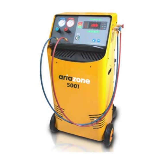
- Page 1 Automotive Air-Conditioning Service Equipment Ariazone 5001 OPERATOR MANUAL...
-
Page 2: Table Of Contents
Contents Page 1. Introduction......................3 2. Safety ........................4 3. Technical Features ....................5 4. Main Parts & Features ................... 6 5. Preparing the machine for the first use ..............8 6. Display descriptions ....................11 7. Refrigerant Cylinder Filling Procedure..............12 8. -
Page 3: Introduction
1. Introduction This Automotive A/C Service Station (Recovery, Recycling, Evacuation and Charging System) is a user-friendly tool specifically designed for the automotive air-conditioning technicians, to carry out the following functions: - Testing air conditioning system - Recover and recycle refrigerant. - Gauge amount of refrigerant recovered from air-conditioning system. - Page 4 2. Important Safety Information's_ This unit is extremely simple and reliable in selecting and performing all its functions. Therefore, the user is not exposed to any risk, if the general safety guidelines reported below are followed, in association with proper use and maintenance of the unit (improper use and maintenance will reduce the safety of the unit).
-
Page 5: Technical Features
3. Technical Features Refrigerant ........R134 a Electronic refrigerant scale ....+/- 10 g resolution Load cell .......... 60kg with 150% overload capacity LP and HP gauges ......AI-D 68 mm kl.1.0 Recovery cylinder ......12 kg Recovery pump ........ FR11G, 275W Recovery rate ........ -
Page 6: Main Parts & Features
4. Main Parts & Features 1. Analog Gauges - Two large analogue gauges display suction and discharge pressures, which are mounted on the front panel for easy viewing by the operator. Pressures are displayed in Bar & PSI and temperatures in degrees Celsius. 2. - Page 7 7. Moisture Indicator - The moisture indicator is conveniently mounted on the console for added protection to indicate the condition of refrigerant and filter change intervals. The following colors correspond to the following moisture content: Green or Blue - Dry, Yellow or Pink - Wet, 8.
-
Page 8: Preparing The Machine For The First Use
5. Preparing the machine for the first use Perform the following steps to prepare the unit before the first use. 1. Remove the nylon wrapped and styrofoam insert behind the cylinder (12). 2. Check to ensure that all of the accessory components are present: - Cylinder (12) - Adapter (17) - Page 9 4. Check the vacuum pump oil level (8). The oil 5. Power up (19) the unit. The unit will perform level should be even with the line on the vacuum a lamp test, whereby all LED displays are pump sight glass when the pump is not running. illuminated.
- Page 10 9. Check that both cylinder valves and liquid hose (16) ball valve are open. LIQUID AND VAPOR HOSES MUST BE CONNECTED TO VAPOR AND LIQUID PORTS ON THE STORAGE CYLINDERS. INCORRECT CONNECTION WILL CAUSE CHARGING TO BE VERY SLOW. 10. Attach the service hoses (5) on the unit. Carefully tight (with fingers only) knurled nut on console bellow hand wheels (blue-left, red-right) and hook up quick couplers (6) to parking brass adapters.
-
Page 11: Display Descriptions
6. Display descriptions Other display descriptions: FILT XXHr - Displays filter life in number of hours after machine is switched on O Hr – Service alarm for maintenance and filter replacement. PAUS - Recovery pause is running, for duration of two minutes. bUSY –... -
Page 12: Refrigerant Cylinder Filling Procedure
7. Refrigerant Cylinder (12) Filling Procedure Connect suction (blue) service hose (5) on storage cylinder by using the brass adapter (17) provided. Open cylinder valve, open service hose (5) quick coupling by winding the wheel clockwise and finnaly open console hand valve (4). Low Pressure gauge (blue) should detect refrigerant pressure from storage cylinder. -
Page 13: Connecting To The A/C System
8. Connecting to the Automotive A/C System Use the service hose (5) quick couplings to connect the hoses to the A/C system service ports, bearing in mind that BLUE must be connected to the low-pressure (suction) side and RED to high pressure (discharge). -
Page 14: Recovery & Recycling Mode
9. Recovery & Recycling Mode The purpose of the Recovery & Recycling mode is to recover refrigerant from the air conditioning system, which will condense, purify and store the liquid refrigerant in the unit cylinder ready for re-use. To initiate the Recovery mode, press the 'UP' key once, followed by 'START' on the console. Display shows (- - - -). - Page 15 If at the end of Recovery process a sufficient vacuum has been maintained, the unit will stop, the display (2) will indicate 'dOnE' and the amount of refrigerant recovered will be displayed in (kg or lb) depending on the operator’s selection. Press 'STOP' on the console, the unit will display "busy"...
-
Page 16: Evacuation Mode
10. Evacuation Mode In the evacuation mode the air and moisture in the air conditioning system is removed and exhausted to the atmosphere. The evacuation mode runs for a predetermined time selected by the operator. To initiate evacuation mode, press the 'UP' key twice, followed by the 'START' key. Select the desired evacuation duration by pressing the 'UP' key to increase or 'DOWN' key to decrease time duration. -
Page 17: New Oil Injection Mode
11. New Oil Injection Mode The purpose of the oil injection mode is to batch a user-defined quantity of refrigerant oil from the graduate reservoirs on the unit to the vehicle air-conditioning system. Important: The unit requires that the air conditioning system has previously been evacuated to a maximum vacuum before this function can be carried out. -
Page 18: Uv Dye Injection Mode
12. UV Dye Injection Mode The purpose of the oil injection mode is to batch a user-defined quantity of UV Dye from the graduate reservoirs on the unit to the vehicle air-conditioning system. Important: The unit requires that the air conditioning system has previously been evacuated to a maximum vacuum before this function can be carried out. -
Page 19: Refrigerant Charge Mode
13. Refrigerant Charge Mode The purpose of the refrigerant charge mode is to batch a user- defined weight of refrigerant into the air-conditioning system. To initiate charging mode, press the 'UP' key three times (or DOWN once), followed by the 'START' key. -
Page 20: Automatic Cylce Mode
14. Automatic Cycle Mode In the Automatic cycle mode, all the operations (Refrigerant Recovering and Recycling, Recovered Oil Drain, Evacuation and Refrigerant Charging) are performed automatically one after the other in ONE CYCLE. Note: During AUTOMATIC mode hand valves (4) on the console must be open. To initiate the Automatic cycle mode, press the “UP”... - Page 21 Set the amount of refrigerant to be charged into the a/c system (with 'UP' key to increase or ‘DOWN’ key to decrease the quantity. Press 'START' key to start automatic mode. (example value only) The unit will perform all tasks (refrigerant recovering, recovered oil drain, evacuation and refrigerant charging) in one automatic cycle.
-
Page 22: Cylinder Air Purge
15. Cylinder Air Purge Once a week before start the unit check if there is air (non-condensable) build up in the refrigerant cylinder (12) during process of recovery. First, measure the ambient temperature. Then read the cylinder pressure on rear gauge (13) and compare it with the temperature pressure chart, affixed to the machine. -
Page 23: Service Procedure
16. Service Procedure The following table describes the service intervals of the unit. Every 100 Working Hours /Once a Year Service. The service alarm will alert the operator for maintenance and filter replacement. Service Kit 100Hr (Vacuum pump Oil - 330ml, Recovery Line Filter, Main Filter Dryer, Service Hoses Rubber Gaskets) Interval Component...
Need help?
Do you have a question about the 5001 and is the answer not in the manual?
Questions and answers
How to calibration when replace new gas cylinder
To calibrate the Ariazone 5001 after replacing the gas cylinder, follow these steps:
1. Place the Empty Cylinder – Position the empty cylinder on the platform, ensuring it is not touching the machine body. Secure it with the strap.
2. Connect Hoses – Attach the cylinder hoses to the cylinder.
3. Power On in Calibration Mode – Press and hold the "UP" button, then switch on the unit using the main power switch at the back.
4. Wait for TARE Display – The display will indicate "TARE". Release the "UP" button.
5. Confirm Calibration – After a beep sound, press the "START" button to complete the zero-weight calibration.
This procedure sets the system to recognize the empty cylinder's weight as 0.00 kg.
This answer is automatically generated