
Related Manuals for ariazone 5001 FAHDF


Summary of Contents for ariazone 5001 FAHDF
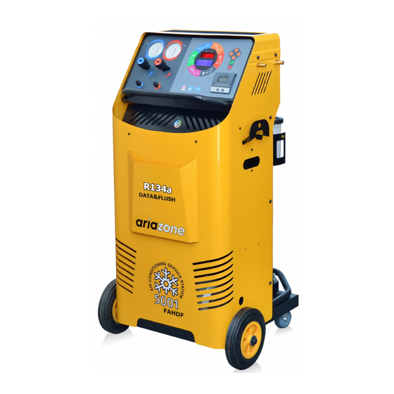
- Page 1 OPERATOR MANUAL ARIAZONE 5001 FAHDF (R134a Data & Flush) Automotive Air Conditioning Service Station OPERATOR MANUAL...
-
Page 2: Table Of Contents
OPERATOR MANUAL Contents Page 1. Introduction ................2. SAFETY FIRST! Important Safety Information's ...... 3. Technical Features ..............4. Main Parts & Features ............. 5. Preparing the Machine for the First Use ........6. Printer ..................7. Refrigerant Cylinder Filling Procedure ........8. -
Page 3: Introduction
OPERATOR MANUAL 1. Introduction_ Fully Automatic Air Conditioning Service Station is a user-friendly tool specifically designed for the automotive air-conditioning technicians, to carry out the following functions: Testing air-conditioning system by comparing pressure readings on HP and LP gauges, Recovery & Recycling the refrigerant from air-conditioning system and gauge amount of refrigerant and oil (if any) recovered from air-conditioning system, Evacuate air-conditioning system, Electronically charge lubricating oil by weight into the air-conditioning system,... -
Page 4: Safety First! Important Safety Information's
OPERATOR MANUAL 2. Important Safety Information's_ This unit is extremely simple and reliable in selecting and performing all its functions. Therefore, the user is not exposed to any risk, if the general safety guidelines reported below are followed, in association with proper use and maintenance of the unit (improper use and maintenance will reduce the safety of the unit). -
Page 5: Technical Features
OPERATOR MANUAL 3. Technical Features_ Refrigerant R134a Electronic refrigerant scale +/- 10 g resolution Load cell 60kg with 150% overload capacity LP and HP gauges D 68 mm kl.1.0 Recovery cylinder 27kg Recovery pump FR11G, 275W Recovery rate up to 400 g/min (liquid state) Vacuum pump 2 stage, 100 l/min (3.5cfm) Vacuum... -
Page 6: Main Parts & Features
OPERATOR MANUAL 4. Main components location_ 1. Low Pressure and High Pressure gauges - Two large analogue gauges display suction and discharge pressures. The gauges are mounted on the front panel for easy viewing by the operator. Pressures are displayed in Bar & PSI and temperatures in degrees Celsius. 2. - Page 7 OPERATOR MANUAL 8. Vacuum Pump Oil Level - Oil level must be checked when the pump is running, the oil level should be even with the horizontal line on the vacuum pump sight glass. Under filling with oil will result in poor vacuum performance. Overfilling can result in oil blowing out from the vacuum pump exhaust.
-
Page 8: Preparing The Machine For The First Use
OPERATOR MANUAL 5. Preparing the Machine for the First Use_ Perform the following steps to prepare the unit before the first use. 1. Remove the shrink wrap and styrofoam insert behind the cylinder (12) (see figure 1). 2. Check to ensure that all of the accessory components are with the unit: - Cylinder (12) - Adapter (17) - Page 9 OPERATOR MANUAL 4. Check the vacuum pump oil level (8). The oil level should be even with the horizontal line on the vacuum pump sight glass when the pump is running. 5. Power up the unit on a main switch (19). The unit will perform a lamp test, whereby all LED displays are illuminated.
- Page 10 OPERATOR MANUAL 7. Mode Selection. To select a mode of operation, press either the "UP" or "DOWN" arrow keys until the LED indicator is beside the desired function. Press 'START' key which will cause the unit to enter the selected mode. Any mode that has been selected can be exited by pressing the 'STOP' key.
-
Page 11: Printer
OPERATOR MANUAL 6. Printer_ The printer is equipped with two keys and green led: >> Paper feed II on line / off line The green led shows the state of the printer: Led constantly ON - Printer in line Led blinking - Printer not in line or no paper Led off - Press II. -
Page 12: Refrigerant Cylinder Filling Procedure
OPERATOR MANUAL 7. Refrigerant Cylinder Filling Procedure (Refrigerant Transfer)_ The cylinder (12) may be filled with refrigerant by the following procedures. Connect the suction (blue) service hose (5) to storage cylinder liquid valve by using the refrigerant cylinder adapter (provided from refrigerant supplier), open liquid valve on storage cylinder, open service hose quick coupling (5) and console blue hand valve (4)... -
Page 13: Connecting To The A/C System
OPERATOR MANUAL 8. Connecting to the A/C system_ Use the service hose (5) quick-connect couplers to connect the hoses to the A/C system service ports, bearing in mind that BLUE must be connected to the low-pressure (suction) side and RED to high pressure (discharge) side. If the system is equipped with a single service port, connect only the relative hose. -
Page 14: Individual (Manual) Function Selection Procedure
OPERATOR MANUAL 9. Individual (Manual) Function Selection Procedures_ With this procedure, all functions: Refrigerant recovery & recycling, A/C System Evacuation, New Oil and/or UV Dye Injection and Refrigerant Charge) can be performed individually (step by step). The values for the quantity of refrigerant recovered, quantity of the oil recovered, vacuum time, quantity of oil injected and quantity of refrigerant charged into the a/c system are automatically printed at the end of each single operation. -
Page 15: Recovery & Recycling Mode
OPERATOR MANUAL 9.1. Recovery & Recycling Mode_ The purpose of the Recovery & Recycling mode is to recover refrigerant from the air conditioning system, which will condense, purify and store the liquid refrigerant in the storage cylinder ready for re-use. To initiate the Recovery mode, press the 'UP' key once, followed by 'START' on the console. - Page 16 OPERATOR MANUAL 9.1.1. Recovered Oil Drain After completing the recovery function, the unit will automatically drain the recovered oil (if any) into recovered oil vessel (9) to electronically calculate amount of oil that has been recovered. The value of the recovered oil will be automatically printed. 9.1.2.
-
Page 17: Evacuation Mode
OPERATOR MANUAL 9.2. Evacuation Mode_ In the evacuation mode the air and moisture in the air conditioning system is removed and exhausted to the atmosphere. The evacuation mode runs for a predetermined time selected by the operator. To initiate evacuation mode, press the 'UP' key twice, followed by the 'START' key. -
Page 18: Oil / Uv Dye Injection Mode
OPERATOR MANUAL 9.3. Oil & UV dye Injection Mode_ The purpose of this function is to batch a user-defined quantity of refrigerant oil or UV dye from the oil reservoir (10) to the vehicle air-conditioning system. Important: The unit requires that the air conditioning system has previously been evacuated to a maximum vacuum before this function can be carried out. -
Page 19: Refrigerant Charge Mode
OPERATOR MANUAL 9.4. Refrigerant Charge Mode_ The purpose of the refrigerant charge mode is to batch a user-defined weight amount of refrigerant into the air-conditioning system. Important: Before start refrigerant charge A/C system MUST be properly evacuated and leak tested. To initiate charging mode, press the 'UP' key four times, followed by the 'START' key. -
Page 20: Automatic Cycle Selection Procedure
OPERATOR MANUAL 10. Automatic Cycle Procedure_ In the Automatic cycle mode, all the operations (Refrigerant Recovering and Recycling, Recovered Oil Drain, Evacuation, New Oil and/or UV Dye Injection and Refrigerant Charging) are performed automatically one after the other in ONE CYCLE. Quantity of the refrigerant recovered, recovered oil, vacuum time, oil injected and refrigerant charged into the A/C... - Page 21 OPERATOR MANUAL Refrigerant Charge selection. The operator can choose between: - MANUAL selection. Set the amount of refrigerant to be charged into the a/c system (with 'UP' key to increase or ‘DOWN’ key to decrease the quantity. The smallest increment of refrigerant charge weight is 0.01 kg (if the units of weight are to lb the smallest increment of refrigerant charge weight is 0.02lb).
- Page 22 OPERATOR MANUAL 10.1. Conditions that will prevent automatic cycle procedure a) If the vacuum test failed. If the vacuum of min -0.85 Bar is not reached after first 90sec of evacuation process, the unit will beep and display TEST FOR LEAK, indicating for possible leak in the a/c system or bad connection of the service hoses.
-
Page 23: Flushing The A/C System With Refrigerant
OPERATOR MANUAL 11. Flushing the A/C system with refrigerant The purpose of the refrigerant flushing mode is to clean (flush) A/C system with high flow rate liquid refrigerant, against the normal flow direction. Imortant: To start flushing mode cylinder (12) must contain minimum 5kg of refrigerant. Connecting the unit on the A/C system for flushing Components of the a/c system such as the compressor, expansion valve and filter dryer should be exchanged with special adapters with large flow. - Page 24 OPERATOR MANUAL Make sure that service hoses (5) are empty (recover refrigerant if not). Connect flushing filter kit on the flushing port (22), located on the rear upper left side of machine. Close red hand valve (4) and disconnect red (dischagre) service hose from control panel (place protective plastic cap on the port below) and connect it on the flush filter kit.
- Page 25 OPERATOR MANUAL First, the A/C system will be evacuated for a five minutes. After evacuation, the A/C system is flushed with liquid refrigerant under the pressure upon the selected time of flushing. The refrigerant which is used to flush the A/C system is purified and return at the cylinder to be used again.
-
Page 26: Cylinder Air Purge
OPERATOR MANUAL 11. Cylinder Air Purge_ Once a week before using the machine check if there is non-condensable (air) build up in the refrigerant cylinder. First, measure the ambient temperature. Then read the cylinder pressure on rear gauge (13) and compare it with the temperature pressure chart, affixed to the machine. If the cylinder pressure is higher than the pressure/temperature chart, there are non- condensable gases (air) in the cylinder (12). -
Page 27: Service Procedure
OPERATOR MANUAL 12. Service Procedure Every 100 Working Hours /Once a Year Service. The service alarm will alert the operator for maintenance and filter replacement. The following table describes the service intervals of the unit. Interval Component Procedure Every 100 Hr / Once a year Main Filter Dryer Replace Every 100 Hr / Once a year... -
Page 28: Unit Settings
OPERATOR MANUAL 14. Unit Settings_ Press and hold depressed the "STOP" button and switch ON the unit (on the main power switch at back). After few seconds, the unit will enter in setup mode and the display will show the list of available settings: TARE –... - Page 29 OPERATOR MANUAL 14.1. Setup Tare (00.00kg calibration) Select TARE and press "START" key. The display will show the following: REFRIGERANT SCALE (Calibrating the weight display to read 00.00kg with an empty cylinder on the unit platform) Place empty cylinder or similar weigh (as unit empty cylinder ~15kg) on the cylinder platform. Connect the cylinder hoses to the cylinder.
- Page 30 OPERATOR MANUAL 14.2. Setup Span (weight calibration) Select SPAN in main <SETTINGS> many and press "START" key. The display will show the following: REFRIGERANT SCALE - (Calibrating the refrigerant cylinder electronic scale) Place known weight (etalon) on top of empty cylinder. Known weigh should be minimum 10kg. Important: Operator should know the right amount (+-10gr) of the weigh he is using.
- Page 31 14.3. Cylinder Settings MAX. REFRIGERANT WEIGHT - Set up of max allowable refrigerant weight in cylinder (12) Use "UP" or "DOWN" keys to set the cylinder weight to 80% of its capacity (20kg max. for 27kg cylinder). Press “START” to save the above settings. MAX.
- Page 32 14.6. Pre-charge (Set the pre-charge value) Set the pre-charge value in order to compensate refrigerant that during the charging process stays trapped into the service hoses. Minimum value is 00.01kg. Recommended pre-charge value for 3m hoses is 00.06kg. Use "UP" or "DOWN" keys to set desired pre-charge value. Press “START” to save the settings 14.7.
- Page 33 14.11. Kg or Lb - Set Metric or Imperial system While machine in “stand by” press and keep depressed “STOP” button for few seconds until numerical display show SET and LED indicator start to flesh. With “START” key select KG (for metric) or LB (for imperial). Press “STOP” to confirm the selection.
- Page 34 The company: Ariazone International Europe 15-ti Korpus bb., 6000 Ohrid, MACEDONIA Hereby declares that the product: Ariazone 5001 FAHD/Flush - Automotive A/C Service Station Meets all requirements of European Directives: 2006/95/EC (ex 73/23/EEC) Low Voltage Directive 2004/108/EC Electromagnetic Compatibility 98/37/EC Machine Directive and subsequent amendments entered in force to the date of declaration.
Need help?
Do you have a question about the 5001 FAHDF and is the answer not in the manual?
Questions and answers