Table of Contents
Advertisement
Quick Links
Advertisement
Table of Contents

Related Manuals for Talex SPRINTER 1500


Summary of Contents for Talex SPRINTER 1500
- Page 1 TALEX Sp. z o.o. ul. Dworcowa 9c, 77-141 Borzytuchom (59) 821 13 40 Phone number e-mail: biuro@talex-sj.pl www.talex-sj.pl ORIGINAL USER MANUAL SPARE PARTS CATALOGUE WARRANTY Self-loading bale wrapper SPRINTER 1500 Borzytuchom 2020 – Revision 02 Page 1 of 129 SELF-LOADING BALE WRAPPER...
- Page 2 Copying, processing of the Instructions Manual and its parts without the manufacturer’s permission is strictly prohibited. TALEX guarantees the efficient operation of the machine, providing it is being used in accordance with the technical and operating conditions specified in this INSTRUCTIONS MANUAL.
-
Page 3: Table Of Contents
Film installation ........................47 Technical servicing ......................... 49 Adjusting the chain tension of the rotary frame ..............49 Adjust the tension of the table roller chain ................51 Adjusting the bale tipper ....................... 52 Page 3 of 129 SELF-LOADING BALE WRAPPER SPRINTER 1500... - Page 4 Maintenance after work ......................78 Machine lubrication ......................79 Storage ..........................82 Troubleshooting ........................83 Disassembly, disposal and environment protection ..............85 Additional equipment ........................ 87 Spare parts catalogue ........................ 88 Page 4 of 129 SELF-LOADING BALE WRAPPER SPRINTER 1500...
- Page 5 Tipper cradle, set ......................120 12.27. Adjustable arm, set ......................121 12.28. Hydraulic system ......................122 Warranty..........................126 List of warranty repairs ......................127 Warranty form ......................... 128 Declaration of Conformity ....................... 129 Page 5 of 129 SELF-LOADING BALE WRAPPER SPRINTER 1500...
-
Page 6: Introduction
Instructions Manual. Please read the information, follow instructions and exercise particular caution. INFORMATION! This symbol indicates additional information, descriptions of how to operate the machine or references to the sections in this manual. Page 6 of 129 SELF-LOADING BALE WRAPPER SPRINTER 1500... -
Page 7: Machine Identification
Each bale wrapper has its rating plate, containing the most important identification data. The plate is affixed on the front beam of the machine bottom frame. Figure 1 Rating plate The rating plate includes: - full name of the manufacturer, Page 7 of 129 SELF-LOADING BALE WRAPPER SPRINTER 1500... - Page 8 - date of manufacture. Figure 2 Rating plate of the running axle The serial number and type of running axle are stamped on the rating plate attached to the running axle beam. Page 8 of 129 SELF-LOADING BALE WRAPPER SPRINTER 1500...
-
Page 9: Rules Of Safe Operation
Any preparations, fitting, dismantling or adjustment can be performed only after the drive has been switched off, the engine stopped, the vehicle immobilised and when all the moving parts of the machine have stopped. Page 9 of 129 SELF-LOADING BALE WRAPPER SPRINTER 1500... - Page 10 Do not stay between the vehicle and the machine when the vehicle engine is running. Working on slopes exceeding 5% is not allowed. Exercise particular caution when working on slopes. Page 10 of 129 SELF-LOADING BALE WRAPPER SPRINTER 1500...
-
Page 11: Residual Risk Assessment
3.2. Residual risk assessment Talex has made every effort to ensure that the design of the machine, and its intended use, do not pose any risk to persons or the environment. Due to the nature of work being done by the bale wrapper and, for example, the inability to completely cover the machine’s working unit, certain risk factors may occur. - Page 12 Read the Instructions Manual. Observe the warnings on the machine. Table Residual risk assessment Page 12 of 129 SELF-LOADING BALE WRAPPER SPRINTER 1500...
-
Page 13: Safety Signs On The Machine
1.5 – Danger of crushing. Do not stand in machine components until at least 50 metres from the the area occupied by the folding bale grab fully stopped working machine. arm. Page 13 of 129 SELF-LOADING BALE WRAPPER SPRINTER 1500... - Page 14 1.11 – Lifting hook location installation method. during transport. 1.14 – Grease nipple symbol denoting the grease 1.13 – Maximum tyre pressure symbol. lubrication point. 1.12 – Information on sensor adjustment. Page 14 of 129 SELF-LOADING BALE WRAPPER SPRINTER 1500...
- Page 15 1.15 – Warning about gloves pressure present hydraulic system. 1.19 – Use hearing 1.20 – Use 1.18 – Use a protectors. safety protective glasses. helmet. Table Safety signs on the machine Page 15 of 129 SELF-LOADING BALE WRAPPER SPRINTER 1500...
- Page 16 Page 16 of 129 SELF-LOADING BALE WRAPPER SPRINTER 1500...
- Page 17 Page 17 of 129 SELF-LOADING BALE WRAPPER SPRINTER 1500...
-
Page 18: Intended Use Of The Machine
The bale wrapper is a welded construction consisting of frames built from steel profiles and interconnected with pins or bolts. The bottom frame to which the unbraked running axle is bolted is Page 18 of 129 SELF-LOADING BALE WRAPPER SPRINTER 1500... - Page 19 The hydraulic system is protected by an oil filter mounted on the left-hand side of the drawbar mounting frame. The electrical system is fitted with a 10 A fuse in the top section of the control unit to protect the controller. Page 19 of 129 SELF-LOADING BALE WRAPPER SPRINTER 1500...
-
Page 20: Technical Specification
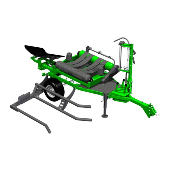
3 – Film cut and hold 4 – Rotary frame 5 – Dispenser post 6 – Film dispenser 7 – Table rollers 8 – Bale grab 9 – Bale tipper Figure 5 Bale wrapper main components Page 20 of 129 SELF-LOADING BALE WRAPPER SPRINTER 1500... - Page 21 3-pin socket Operation capacity [pcs/h] Noise level [dB] Number of wheels [pcs.] Size of tyre 350/50-16 Tyre air pressure [kPa] Table Bale wrapper technical and operational data Page 21 of 129 SELF-LOADING BALE WRAPPER SPRINTER 1500...
-
Page 22: Operating Principle
(7) captures the bale and then puts it down in a vertical or horizontal position. Figure 6 Bale wrapper operating principle (1) grab, (2) main frame, (3) rotary frame, (4) table roller and belt assembly, (5) film dispenser, (6) film cut and hold Page 22 of 129 SELF-LOADING BALE WRAPPER SPRINTER 1500... -
Page 23: Film Dispenser
(9) and fastened with tensioning gears (6). The tension is also adjusted by the position of the pressure screw (5). An actuator (12) is responsible for the movement of the scraper arm (11). Page 23 of 129 SELF-LOADING BALE WRAPPER SPRINTER 1500... -
Page 24: Rotary Frame
Figure 8 Movement of the rotary frame (1) chain drive, (2) driving table roller, (3) table roller and belt assembly, (4) belts, (5) bearing unit, (6) side bumper, (7) outer holder Page 24 of 129 SELF-LOADING BALE WRAPPER SPRINTER 1500... -
Page 25: Bale Tipper (Unloading)
(6). The bale will be placed on the left side of the cradle in a vertical position (with its bottom on the ground). Page 25 of 129 SELF-LOADING BALE WRAPPER SPRINTER 1500... -
Page 26: Cut And Hold
It is important that the unloading movement from the tipper is as smooth as possible regardless of the weight of the wrapped bale. For a description of the drop speed control, see Section 7.3. 5.3.4 Cut and hold Page 26 of 129 SELF-LOADING BALE WRAPPER SPRINTER 1500... - Page 27 (8). When the machine is started, the first cycle starts with the accumulation of pressure in the accumulator, which is automatically repeated every 10 cycles. Remove the blade guard before starting work, see Figure 12. Page 27 of 129 SELF-LOADING BALE WRAPPER SPRINTER 1500...
- Page 28 Before you start wrapping, the blade guard in Figure 12 must be removed. Page 28 of 129 SELF-LOADING BALE WRAPPER SPRINTER 1500...
-
Page 29: Electrical System
7-pin plug connection wire. An overview diagram of the electrical system of the bale wrapper is shown in Figure (14). Page 29 of 129 SELF-LOADING BALE WRAPPER SPRINTER 1500... - Page 30 (GP) 7-pin plug connector, (LP) right multifunction tail lamp, (LL) left multifunction tail lamp Designation Function Ground Power supply +12 V Left direction indicator Brake light Tail light, left Tail light, right Right direction indicator Table 4 Symbols for socket connections Page 30 of 129 SELF-LOADING BALE WRAPPER SPRINTER 1500...
- Page 31 3A - 3B Solenoid valves for table tilt, bale tipper, scraper 4A - 4B Solenoid valves for film cut and hold Proportional solenoid valve Balanced solenoid valve Table 5 Symbols for control system Page 31 of 129 SELF-LOADING BALE WRAPPER SPRINTER 1500...
-
Page 32: Hydraulic System
Before carrying out repair or maintenance, make sure that the system is depressurised. Hydraulic oils should be stored in original containers or in packaging adapted to their storage, paying particular attention to the effect of hydrocarbons. Page 32 of 129 SELF-LOADING BALE WRAPPER SPRINTER 1500... - Page 33 It drives the cut and hold actuator, which is designed to perform two functions: - cut off the film from a bale to be put down, - hold the film on the side of the dispenser before the next cycle. Page 33 of 129 SELF-LOADING BALE WRAPPER SPRINTER 1500...
-
Page 34: Machine Operation
Before every time the machine is used, its technical condition needs to be checked, and especially the condition of units like rotation transmission system, hydraulic and electrical systems. Page 34 of 129 SELF-LOADING BALE WRAPPER SPRINTER 1500... -
Page 35: Installing The Bale Wrapper
Figure 18 Coupling bale wrapper with a tractor (1) drawbar eye, (2) pin, (3) hydraulic hoses, (4) tractor hitch Coupling the bale wrapper with the tractor should be performed on hard and even ground. Page 35 of 129 SELF-LOADING BALE WRAPPER SPRINTER 1500... -
Page 36: Levelling The Bale Wrapper
(3) from the bale grab (Figure 20) by removing the locking pin (2) from the pin (1) to remove the flat bar and put it securely in the working position (Figure 21). Page 36 of 129 SELF-LOADING BALE WRAPPER SPRINTER 1500... - Page 37 (1) pin, (2) locking pin, (3) locking flat bar Figure 21 Grab securing in the working position (1) Locking flat bar, (2) locking pin After hitching the machine with the tractor inst. 6.2, lift the support foot, Figure 22. Page 37 of 129 SELF-LOADING BALE WRAPPER SPRINTER 1500...
-
Page 38: Principles For Driving On Public Roads
It is forbidden to carry persons on the machine; Only disconnect the machine from the tractor on level ground and after you placed wedges to prevent rolling down. Page 38 of 129 SELF-LOADING BALE WRAPPER SPRINTER 1500... - Page 39 Caution! Driving the bale wrapper on public roads with a bale loaded is not allowed. Page 39 of 129 SELF-LOADING BALE WRAPPER SPRINTER 1500...
-
Page 40: Switching Between Methods For Unloading Bales
1. Rolling the bale behind the bale wrapper Figure 24 Unloading setting (1) Adjustable arm 2. Tipping the bale to the side (bottom), to the left of the bale wrapper. Figure 25 Unloading setting (1) Adjustable arm Page 40 of 129 SELF-LOADING BALE WRAPPER SPRINTER 1500... -
Page 41: Bale Grab Adjustment
(3) depends on the diameter of the baled crop. Small diameter bales are loaded when the arm is at its shorter setting, whereas larger bales – at its longer one. The adjustable arm (3) must be locked with the screw (4) against being pulled out. Page 41 of 129 SELF-LOADING BALE WRAPPER SPRINTER 1500... -
Page 42: Displacement Of The Tractor's Drive Centreline In Relation To The Bale
Adjustments are made according to the diameter of the wrapped bales, where conventionally there are two diameters: 1200 and 1500 mm. Dimension “X” for individual diameters: Bale diameter [mm] Dimension X [mm] 1200 1850 1500 1950 Page 42 of 129 SELF-LOADING BALE WRAPPER SPRINTER 1500... -
Page 43: Film Adjustment
Method two involves drawing 2 parallel lines at a distance of 100 mm on a roll placed in the dispenser. As a result of the film stretching, the dimension should increase. The correct distance between lines at the 55-70% film pre-tension must be between 155 and 170 mm. Page 43 of 129 SELF-LOADING BALE WRAPPER SPRINTER 1500... - Page 44 The dimensions of the film are approximate and are given by the manufacturer of the 70% extensible film. Before you start operating the bale wrapper, read the film manufacturer's instructions for setting the pre- tension carefully. Page 44 of 129 SELF-LOADING BALE WRAPPER SPRINTER 1500...
-
Page 45: Adjusting Film Tension
- If the film tension is too weak, lift the screw by turning the lever (1) to the right. 3. Tighten the jam nut (2). 4. Check the tension of the film and repeat the procedure if necessary. Page 45 of 129 SELF-LOADING BALE WRAPPER SPRINTER 1500... -
Page 46: Adjusting Film Dispenser Height
(1) to move the dispenser unit (2) to the optimum position (Figure 30). The dispenser height should be adjusted after the first bale is loaded. Figure 30 Dispenser height adjustment (1) dispenser post turn lever, (2) dispenser unit, (3) film, (4) bale Page 46 of 129 SELF-LOADING BALE WRAPPER SPRINTER 1500... -
Page 47: Film Installation
Turn the roller unit (1) in such a way that one of them rests on the film. Thread the section of film you unrolled through the rollers according to the diagram shown on the dispenser decal (Figure 32). Page 47 of 129 SELF-LOADING BALE WRAPPER SPRINTER 1500... - Page 48 For installing the 750 mm wide film you need to adjust the film dispenser to this type of rolls. The use of the wider film requires changing the gear ratio of the turntable. For details, refer to Section 7.5. Page 48 of 129 SELF-LOADING BALE WRAPPER SPRINTER 1500...
-
Page 49: Technical Servicing
Figure 34 Adjusting the chain tension of the rotary frame (1) bolts, (2) motor plate, (3) tensioner screw, (4) tensioner nut Follow the procedure for tensioning the chain of the rotary frame: Page 49 of 129 SELF-LOADING BALE WRAPPER SPRINTER 1500... - Page 50 If chain tension adjustment does not bring the desired effect, it may indicate wear (excessive stretch) of the chain, which is a normal sign in this type of drives. In this case, replace the chain with a new one. Page 50 of 129 SELF-LOADING BALE WRAPPER SPRINTER 1500...
-
Page 51: Adjust The Tension Of The Table Roller Chain
9. Check rubber belt tensions and make adjustments if necessary. Caution! Check the tension of the table rollers’ chain after 20 cycles, and then every 200 cycles, as well as when replacing bearings or sprocket of the driving table roller. Page 51 of 129 SELF-LOADING BALE WRAPPER SPRINTER 1500... -
Page 52: Adjusting The Bale Tipper
Turn to the right (-) to reduce the speed of the drop. Turn to the left (+) to increase the speed of the drop. Page 52 of 129 SELF-LOADING BALE WRAPPER SPRINTER 1500... -
Page 53: Adjusting The Tension Of The Belts
If the stretch of the belts is greater than the adjustment range, the belts must be replaced. All repairs, adjustments and maintenance works must be carried out when the machine is stationary and secured. Page 53 of 129 SELF-LOADING BALE WRAPPER SPRINTER 1500... -
Page 54: Changing Film Width
Fit the sprocket (5) or (6) depending on the width of the film, as required in Table 7 10. Screw in the lock screw (3) connecting the wheel to the hub (7) with a size 13 wrench. 11. Attach the circlip (4). Page 54 of 129 SELF-LOADING BALE WRAPPER SPRINTER 1500... -
Page 55: Changing The Lower Holder Position Of The Film Dispenser Post
(2) with the screw (4). After checking the correctness of the tension of the film, secure the position of the screw (4) against unscrewing with the jam nut (3). Page 55 of 129 SELF-LOADING BALE WRAPPER SPRINTER 1500... -
Page 56: Maintaining The Running Axle
- Set the steering of the tractor for a straight ride. Place wedges under the bale wrapper's wheel. Make sure that the machine does not roll during the check. Lift the wheel on the opposite side of the chocks. Page 56 of 129 SELF-LOADING BALE WRAPPER SPRINTER 1500... -
Page 57: Removing Play In The Running Axle Bearings
Loosen the nut by at least 1/3 turn to line up the nearest groove of the nut with the hole in the running axle stud. The wheel should turn without any excessive resistance - The nut must not be over-tightened. Too strong tightening is not recommended due to the worse bearing operation. Page 57 of 129 SELF-LOADING BALE WRAPPER SPRINTER 1500... -
Page 58: Mounting And Dismantling Wheel, Checking Nuts For Tightness
Put the wheel on the hub, tighten the nuts so that the rim fits tightly against the hub. Lower the bale wrapper, tighten the nuts according to the recommended torque and the order shown in Figure 42. Page 58 of 129 SELF-LOADING BALE WRAPPER SPRINTER 1500... - Page 59 The highest tightening accuracy is achieved with a torque wrench. Before you start tightening, make sure that the correct tightening torque is set. Wrench arm selection. Page 59 of 129 SELF-LOADING BALE WRAPPER SPRINTER 1500...
-
Page 60: Checking Air Pressure, Assessing The Technical Condition Of Tyres And Steel Rims
Pressure control and visual inspection of steel rims: every 1 month of operation, every week for intensive use, if required. Page 60 of 129 SELF-LOADING BALE WRAPPER SPRINTER 1500... -
Page 61: Control System
Before connecting electrical cables, make sure that they are not damaged and secure them properly, if necessary. Control unit Figure 43 Control unit (1) emergency push button, (2) fuse 10 A, (3) display, (4) display buttons, (5) control buttons, (6) power cable, (7) control cable Page 61 of 129 SELF-LOADING BALE WRAPPER SPRINTER 1500... -
Page 62: Description Of Functions Of The Control Unit
Cancels selection and exits the selected screen Moves cursor up Moves cursor down Inserts a dot Moves cursor left Moves cursor right Lifts the bale grab Enters “1” Lowers the bale grab Enters “6” Page 62 of 129 SELF-LOADING BALE WRAPPER SPRINTER 1500... - Page 63 Cuts and holds the film Enters “4” Releases the film Enters “9” Goes to the menu Enters “5” Lists recent faults Enters “0” Display keys Table 9 Description of functions of the control unit Page 63 of 129 SELF-LOADING BALE WRAPPER SPRINTER 1500...
-
Page 64: Operating Modes
Once the grab lock is removed and confirmed, the main screen with basic information is displayed. Depending on the selected operating mode, the main screen can vary slightly: Automatic mode screen Page 64 of 129 SELF-LOADING BALE WRAPPER SPRINTER 1500... -
Page 65: Auto Mode
After selecting the display key “ROTATIONS” , you can change the number of bale wraps to 16, 24 or choose custom number of turns. To execute a change, set the selected quantity using the arrows and confirm with . Page 65 of 129 SELF-LOADING BALE WRAPPER SPRINTER 1500... -
Page 66: Semi-Auto Mode
This activates an automatic operation and once completed, pauses to wait for the next signal to be executed. The individual sections are executed separately after they are started. The other Page 66 of 129 SELF-LOADING BALE WRAPPER SPRINTER 1500... -
Page 67: Manual Mode
In the “MANUAL” mode, all operations are confirmed by the operator who holds down a control button for the section required. Removing your finger from the button terminates the operation of the section. Keys for controlling sections: Manual control screen: Page 67 of 129 SELF-LOADING BALE WRAPPER SPRINTER 1500... -
Page 68: Menu
Changing the operating mode To change the operating mode , move to the menu by pressing and highlight the cursor pressing ; use arrows to select the “Work mode” item and touch to confirm Page 68 of 129 SELF-LOADING BALE WRAPPER SPRINTER 1500... -
Page 69: Changing The Bale Weight
; use arrows to select the “Statistics” item and touch to confirm .. The information in statistics may be restarted to obtain a new measurement. The tab contains information about: Page 69 of 129 SELF-LOADING BALE WRAPPER SPRINTER 1500... - Page 70 The number of cycles completed on a given day and all the cycles the machine has ever completed. After selecting the restart, only the day's count of cycles can be reset. Confirm the restart with the key on the screen. Cycle times Page 70 of 129 SELF-LOADING BALE WRAPPER SPRINTER 1500...
- Page 71 The average time from the last 5 complete cycles is given. Runtime Time left before inspection An approximate time before the next machine inspection is also given. Page 71 of 129 SELF-LOADING BALE WRAPPER SPRINTER 1500...
-
Page 72: Changing Speed In Automatic And Semi-Automatic Modes
8.5 Changing speed in automatic and semi-automatic modes You can change the speed over 3 basic settings: slow, medium, fast, or choose custom settings. Changing the speed in AUTO and Auto/Manual modes to custom settings requires a password. Page 72 of 129 SELF-LOADING BALE WRAPPER SPRINTER 1500... - Page 73 Entering a password and confirming involves the risk of exceeding the safe operating speed of the machine, so it is forbidden for an unauthorised person to change parameters. Caution! The manufacturer's approval is required for changing the setpoints on your own. Custom mode setpoints. Page 73 of 129 SELF-LOADING BALE WRAPPER SPRINTER 1500...
-
Page 74: Contact Details
8.6 Contact details To view the contact details, move to the menu by pressing and highlight the cursor by pressing use arrows to select the “Kontakt” item and touch to confirm . The screen will then display the name of the machine manufacturer, the country of origin and the contact telephone. 8.7 Date and time settings To set the date and time, move to the menu by pressing and highlight the cursor by pressing... -
Page 75: Choosing The Language
8.8 Choosing the language To choose the language, move to the menu by pressing and highlight the cursor by pressing use arrows to select the “Język” item and touch to confirm . Move the cursor up and down to select the language and confirm with . 8.9 Application update To make an update, move to the menu by pressing and highlight the cursor by pressing... -
Page 76: Last Fault
The system will ask again if you want it to upgrade to a new version: to confirm, press , to cancel, press 8.10 Last fault There is also a key on the panel that informs the operator about the status of the machine's safety sensors. - Page 77 If the messages are displayed, set the items to the required position. If the item is correct but the error is still displayed, check the sensor for offset range or damage.
-
Page 78: Maintenance
When the primer coat is dry, apply the paint coat. Replace damaged and worn out parts with new ones. Check all the screwed joints, tighten the loose screws and nuts according to Table . The manufacturer of the machine, Talex, provides all spare parts. Caution! Nuts with polyamide insert –... -
Page 79: Machine Lubrication
1050 1220 Table 10 Tightening torque values for bolts and nuts. Lubricate the bale wrapper according to the Instructions Manual – 9.2 Machine lubrication . All information signs affixed on the machine must be kept clean. Machine lubrication Appropriate periodical maintenance works considerably decrease the wear and tear of mating components and additionally protect against corrosion. - Page 80 Pre-seasonally, every Table roller drive Machine grease 30 hours of work or 1x gear for chain drives a year Pre-seasonally, every Film dispenser 30 hours of work or 1x Machine grease gears a year 10 hrs or at least 1x a Lower spindle Machine grease year...
- Page 81 Pre-seasonally, every 10 hours of work or 1x Tilt actuator Machine grease a year Pre-seasonally, every Table roller 10 hours of work or 1x Machine grease bearings a year Film scraper Pre-seasonally, every actuator 10 hours of work or 1x Machine grease fasteners a year...
-
Page 82: Storage
Pre-seasonally, every Support foot 30 hours of work or 1x Machine grease a year Pre-seasonally, every Hitch bolt 10 hours of work or 1x Machine grease a year Pre-seasonally, every Silicone spray 10 hours of work or 1x Bumper pin lubricant a year Pre-seasonally, every... -
Page 83: Troubleshooting
environmental factors causing corrosion and ageing of any materials. Additionally, during long downtimes (e.g. winter) it is recommended to: Lubricate any moving joints with fresh grease; Apply commercially available anti-corrosion silicone based agents on the surface of bolts and pins to inhibit the corrosion onset. - Page 84 wrapper. Tractor pump failure. Repair a defective system. Hydraulic pump delivery flow rate of Reduce the delivery flow rate. Hydraulic oil does not the tractor too high. return from the Check the hoses for kinks or actuators. Hose blockage. damage. Replace if necessary. Check the oil filter and replace Actuator travel range if necessary.
-
Page 85: Disassembly, Disposal And Environment Protection
jammed. Check dispenser bearings, sprockets and gears and replace if necessary. Reduce the rotational speed during wrapping. Ensure Irregular bale shape. correct bale formation. Film parts stick with each other in Check the film tension. the wind. Reduce the rotational speed Rotational speed too high. - Page 86 protection regulations. Prevent oil leakage throughout the period of use of the machine, as oil may pollute the environment. Protect your hands (and body) against injuries, and the harmful effects of lubricants and oils. Use personal equipment measures and tools which are in good mechanical condition. Machine elements, which when dismounting can move or rotate, must be properly secured.
-
Page 87: Additional Equipment
11. Additional equipment Additional equipment is only available on request in the premium version by prior agreement with the manufacturer. Table 12 presents additional equipment. VERSION EQUIPMENT STANDARD PREMIUM Additional film dispenser Work cycle auto-start Workstation lighting Turning support wheel Radio control Additional film storage Table 12 Refitting options for the premium version... -
Page 88: Spare Parts Catalogue
Such changes may not always be updated in the User Manual and in the spare parts catalogue. Individual drawings may differ from the actual look of the parts. TALEX Spółka z ograniczoną odpowiedzialnością Spółka komandytowa ul. Dworcowa 9C 77-141 Borzytuchom Phone number (059) 821 13 40 www.talex-sj.pl... -
Page 89: General Design
12.1. General design... - Page 90 General design Item Part No. Title Quantity Index/Section No. OW 01.00.00.00 Bottom frame, set P810000/12.2. Bottom frame, set OW 02.00.00.00 Turntable slide base P810109/12.11. Turntable slide base, set OW 03.00.00.00 Rotary frame, set P810075/12.14. Rotary frame, set OW 04.00.00.00 Film cut and hold P810119/12.16.
- Page 91 12.2. Bottom frame, set...
-
Page 92: Bottom Frame, Set
Bottom frame Quantit Index/Section Item Part No. Title 1 OW 01.01.00.00 Welded frame 1 P810008 2 OW 01.02.00.00 Drawbar, set 1 12.3. 3 OW 01.03.00.00 Hitch fixing, set 1 12.4. 4 OW 01.04.00.00 Counterweight, set 1 P810054/12.5. 5 OW 01.05.00.00 Support foot 1 12.6. - Page 93 12.3. Drawbar, set Drawbar, set Item Part No. Title Quantity Index/Section No. 1 OW 01.02.00.00 Drawbar 1 P810040 2 Hex. nut.M16-8-galv.-self-lock. Hex. nut.M16-8-galv.-self-lock. 10 T000294 3 Washer Φ 16-galv. Washer Φ 16-galv. 20 T000460 4 Hex screw M16x50-8.8-galv. Hex screw M16x50-8.8-galv. 10 T000781...
-
Page 94: Hitch, Set
12.4. Hitch, set Hitch fixing, set Item Part No. Title Quantity Index OW 01.03.00.00 Hitch fixing P810050 Hitch eye Hitch eye T002574 Washer Φ 16-galv. Washer Φ 16-galv. T000460 Hex screw M16x170-8.8-galv. T002772 Hex screw M16x170-8.8-galv. OW 01.03.00.01 P810005 Hitch fixing spacer Self-locking nut M16 Self-locking nut M16 T000294... - Page 95 Counterweight, set Item Part No. Title Quantity Index OW 01.04.01.00 Counterweight P810056 OW 01.04.00.01 P810055 Round head bolt M6x10 galv. Round head bolt M6x10 galv. T000940 Lock wash. Φ 6-galv. Lock wash. Φ 6-galv. T002773 12.6. Support foot, set...
- Page 96 Support foot, set Item Part No. Title Quantity Index OW 01.05.00.00 Support foot P810061 Hex screw M12x40-8.8-galv. Hex screw M12x40-8.8-galv. T000757 T000291 Hex. nut M12-8-GAL-self-cl. Hex. nut M12-8-GAL-self-cl. Washer Φ 12-galv. Washer Φ 12-galv. T000458 12.7. Safety arm, set...
- Page 97 Safety arm, set Item Part No. Title Quantity Index OW 01.06.01.00 Safety arm P810064 Hex nut M14-8-galv.-self-lock. Hex nut M14-8-galv.-self-lock. T000293 Chain Chain T000167 T000987 Double locking pin Double locking pin 12.8. Manifold fixing, set...
- Page 98 Manifold fixing, set Item Part No. Title Quantity Index OW 01.07.00.00 Manifold fixing Bush Bush T002414 Washer Φ 10-galv. Washer Φ 10-galv. Hex screw M10x25-8.8-galv. Hex screw M10x25-8.8-galv. Hex. nut.M10-8-GAL self-cl. Hex. nut.M10-8-GAL self-cl. T000292 Lock washer Φ 10-galv. Lock washer Φ 10-galv. 12.9.
- Page 99 Film storage, set Item Part No. Title Quantity Index OW 01.09.00.00 Film storage P810068 Pipe caps Pipe caps T002648 T000805 Hex screw M8x25-8.8-GAL Hex screw M8x25-8.8-GAL Washer Φ 8-galv. Washer Φ 8-galv. T000471 Nut M8-galv.-self-lock. Self-locking nut T000256...
- Page 100 12.10. Platform, set Platform, set Item Part No. Title Quantity Index OW 01.00.00.02 Platform P810002 Round head bolt M8x25 galv. Round head bolt M8x25 galv. T000806 Washer Φ 8-galv. Washer Φ 8-galv. T000471 Nut M8-galv.-self-lock. Nut M8-galv.-self-lock. T000256...
- Page 101 12.11. Turntable slide base, set...
-
Page 102: Turntable Slide Base, Set
TURNTABLE SLIDE BASE, SET Index/Section Item Part No. Title Quantity OW 02.01.00.00 Slide base frame P810110 OW 02.02.00.00 Rotary base P810136 Sensor Unloading sensor T001137 Rotary frame rotation chain Rotary frame rotation chain 24 links T002613 Cone wheel, big Cone wheel, big T002593 Bolt M8x20 Bolt M8x20... - Page 103 12.12. Rotary base ROTARY BASE, SET Index/Section Item Part No. Title Quantity OW 02.02.01.00 P810137 OW 02.02.02.00 P810140 Grease nipple M10x1 Grease nipple M10x1 T000643 Bearing Bearing T002621 Washer mb12 Washer mb12 T002630 T002789/ Shim Φ 30 Shim Φ 30 T000514 Nut KM12 Nut KM12...
- Page 104 12.13. Drive assembly DRIVE ASSEMBLY, SET Index/Section Item Part No. Title Quantity OW 02.03.00.01 Motor fixing P810144 OW 02.03.00.03 Washer P810316 OW 02.03.01.00 Motor gear wheel P810146 Key 8x7x32 Key 8x7x32 T000953 OW 02.03.00.02 Washer P810145 Lock washer Φ 8 Lock washer Φ...
- Page 105 12.14. Rotary frame, set...
-
Page 106: Rotary Frame, Set
ROTARY FRAME, SET Item Part No. Title Index Quantity OW 03.01.00.00 Rotary frame P810082 OW 03.00.00.08 Frame rotation chain guard - sensor P810078 OW 03.03.00.00 Chain guard, set P810102 Circlip Z22 Circlip Z22 T002775 OW 03.00.00.13 Table roller drive wheel gear P810099 Key 8x7x25 Key 8x7x25... - Page 107 MIDDLE FRAME SET Item Part No. Title Quantity Index OW 03.03.01.00 Guard rear wall P810103 OW 03.03.02.00 Chain guard P810106 Washer Φ 6 Washer Φ 6 T000469 Lock washer Φ 6 Lock washer Φ 6 T002773 Bolt M6x16 Bolt M6x16 T000800...
-
Page 108: Film Cut And Hold, Set
12.16. Film cut and hold, set LEFT SIDE FRAME SET Index/Section Item Part No. Title Quantity P810126 OW 04.01.00.00 Cut and hold frame OW 04.00.00.01 Bend clamp, heavy-duty P810120 OW 04.00.00.02 Heavy-duty clamp P810121 Washer Φ 16 Washer Φ 16 T000460 Bolt M16x90 np.gw. - Page 109 Button screw M6x12 Button screw M6x12 T000940 Lock washer Φ 6 Lock washer Φ 6 T002773 Nut M24 Nut M24 T000290 OW 04.00.00.08 Blade guard P810340 Wing bolt M6x10 Wing bolt M6x12 T000940 Spring Spring T000674 OW 04.00.00.06 Bumper pin P810125 Rubber bumper Rubber bumper...
-
Page 110: Dispenser Post, Set
12.17. Dispenser post, set DISPENSER POST, SET Item Part No. Title Quantity Index OW 05.01.00.00 Welded dispenser post P810159 OW 05.02.00.00 Film puller arm P810170... - Page 111 Circlip Z25 Circlip Z25 T000424 OW 05.00.00.09 Poppet P810156 Poppet bearing Poppet bearing T000212 Circlip W62 Circlip W62 T000418 Sliding sleeve Sliding sleeve T002699 OW 05.04.00.00 Bottom pressure screw P810177 Profile stopper Profile stopper 80x80 T000967 Spring-type straight pin 6x45 Spring-type straight pin 6x45 T002777 Bolt M16x45...
-
Page 112: Film Dispenser, Set
12.18. Film dispenser, set FILM DISPENSER, SET Item Part No. Title Quantity Index OW 06.01.00.00 Dispenser rack P810185 OW 06.04.00.00 Dispenser roller No. 2 Size 11.21 OW 06.02.00.00 Gear cover P810190 spring 5223/89-036/0 spring 5223/89-036/0 T000677 Bolt M6x45 Bolt M6x45 T000801 Nut M12 Nut M12... -
Page 113: Dispenser Roller No. 1
12.19. Dispenser roller No. 1 DISPENSER ROLLER NO. 1, SET Item Part No. Title Quantity Index Dispenser roller Dispenser roller P810194 OW 06.03.00.05 Gear wheel, big P810199 Lock washer Φ 6 Lock washer Φ 6 T002773 Bolt M6x16 Bolt M6x16 T000800 Bolt M6x45 Bearing... -
Page 114: Dispenser Roller No. 2
12.20. Dispenser roller No. 2 DISPENSER ROLLER NO. 2, SET Item Part No. Title Quantity Index Dispenser roller Dispenser roller P810200 OW 06.04.00.01 Gear wheel, small P810201 Lock washer Φ 6 Lock washer Φ 6 T002773 Bolt M6x16 Bolt M6x16 T000800 Bolt M6x45 Bolt M6x45... - Page 115 12.21. Table rollers TABLE ROLLERS, SET Item Part No. Title Quantity Index OW 07.01.00.00 Idle table roller, set Size 11.23. OW 07.02.00.00 Driving table roller, set Size 11.23 Belt 3226x200x5 Rubber belt (conveyor belt) T002625...
-
Page 116: Idle Table Roller, Set
12.22. Idle table roller, set IDLE TABLE ROLLER, SET Item Part No. Title Quantity Index OW 07.01.01.00 Idle table roller P810204 Table roller bearing (209) Table roller bearing T001012 Washer ф 14 Washer ф 14 T000459 Lock washer ф 14 Lock washer ф... -
Page 117: Driving Table Roller
12.23. Driving table roller DRIVING TABLE ROLLER, SET Item Part No. Title Quantity Index OW 07.02.01.00 Driving table roller P810213 Table roller bearing (209) Table roller bearing T001012 OW 07.03.00.00 P810338 Gear wheel 3/4", Z21 OW 07.02.00.01 (interchangeable with OW P810339 07.02.00.02) Gear wheel 3/4", Z35... -
Page 118: Bale Grab, Set
12.24. Bale grab, set BALE GRAB, SET Item Part No. Title Quantity Index OW 08.01.00.00 Grab arm P810226 OW 08.02.00.00 Adjustable arm P810238 OW 08.03.00.00 Buffer P810243 Bolt M12x40 Bolt M12x40 T000757 Self-locking nut M12 Self-locking nut M12 T000291 Washer Φ 12 Washer Φ... -
Page 119: Bale Tipper, Set
12.25. Bale tipper, set BALE TIPPER, SET Item Part No. Title Quantity Index OW 09.01.00.00 Outer frame P810251 OW 09.02.00.00 Tipper cradle, set Size 11.27 OW 09.04.00.00 Adjustable arm, set P810305 Adjustable arm locking pin Adjustable arm locking pin T000990/2 Spring-type straight pin 6x45 Spring-type straight pin 6x45 T002777... -
Page 120: Tipper Cradle, Set
12.26. Tipper cradle, set TIPPER CRADLE, SET Item Part No. Title Quantity Index OW 09.02.01.00 Tipper slide base P810269 OW 09.02.02.00 Cradle frame P810283 OW 09.02.00.02 Sheet P810268 OW 09.02.04.00 Cradle corner P810300 Nut M 10 self-locking Nut M 10 self-locking T000292 Washer ф... -
Page 121: Adjustable Arm, Set
12.27. Adjustable arm, set ADJUSTABLE ARM, SET Item Part No. Title Quantity Index OW 09.04.01.00 Adjustable arm P810308 OW 09.04.00.02 Arm disc P810307 OW 09.04.00.01 Arm disc pin P810306 Spring-type straight pin fi8x40 Spring-type straight pin fi8x40 T000083... -
Page 122: Hydraulic System
12.28. Hydraulic system... - Page 123 Hydraulic system Hoses: Item Quan Description Title Index tity P51/P51 22x1.5 2SN DN13 L-2380 Power supply cable T002709 P51/P51 22x1.5 2SN DN13 L-1000 Filter hose T002905 P51/P51 22x1.5 2SN DN16 L-3000 Return hose T002707 P51/P52 18x1.5 2SN DN10 L-2350 Bale grab hoses T002708 P51/P52 18x1.5 2SN DN10 L-2500 Bale grab hoses...
- Page 124 Connections: Quick release coupling 12.5 M18*1.5 Quick release coupling (Euro) T000995 Connector G1/4” – M18x1.5 Straight connector T000580 Connector G1/4”-M16x1.5 Straight connector T000583 Connector AB G1/4” – M16x1.5 Angle connector T001026 SJ90 -04 ¼’’ BSP D18 Rotary joint T002636 DN-147 M18*1.5 12L T-connection T001045 Other:...
- Page 125 Item Description Title Quantity Index OW 01.00.00.09 Manifold fixing P810072 Hydraulic manifold block Manifold T002779 Controlled non-return valve “Lock” T001451 SB-B2-0103AL Regulator T002697 Straight coupling G1/2’ / M18x1.5 (BB) Straight coupling T000578 M18x1.5 (AB) Curved connector T002730 Elbow coupling M18x1.5 (AB) Elbow coupling T001032 T-connection M18x1.5 (BAB)
-
Page 126: Warranty
13. Warranty WARRANTY CERTIFICATE Serial No. Type ……………………… ……………………… Year of Quality Control ……………………… ……………………… manufacture (KJ) Under the warranty, the manufacturer undertakes to repair, free of charge, any physical defects revealed during the warranty period, i.e. 12 months from the date of sale. The manufacturer will be exempt from liability under the warranty in case of: ... -
Page 127: List Of Warranty Repairs
14. List of warranty repairs Filled in by the manufacturer Date of complaint submission: ________________ Date of complaint submission: ________________ Scope of repair and parts replaced: _________ Scope of repair and parts replaced: _________ _____________________________________ _____________________________________ _____________________________________ _____________________________________ _____________________________________ _____________________________________ Date of complaint resolution: _______________ Date of complaint resolution: _______________ Warranty extended until: ____________... -
Page 128: Warranty Form
15. Warranty form WARRANTY FORM NO. ……………… Full name :…........................Address :............................Postal code :……............................ City :……........................Telephone number:…..........................E-mail address :…………………................Complaint submission method:………...…………………………………………………………….. Name of the subject of complaint: ....................Name of the dealer :…………….…………………………………........Proof of purchase - VAT invoice No.......dated ......20…..Description of fault / damage:…………..................... -
Page 129: Declaration Of Conformity
• ……………………………. This declaration of conformity shall cease to be valid if the machine is modified in any way without the consent of the Talex Sp. z o.o. Conformity with the requirements of the directives and standards has been ascertained based on the tests conducted by: ……………………………………………………………………………………………………………………………………………………………………….
Need help?
Do you have a question about the SPRINTER 1500 and is the answer not in the manual?
Questions and answers