Sign In
Upload
Download
Table of Contents
Contents
Add to my manuals
Delete from my manuals
Share
URL of this page:
HTML Link:
Bookmark this page
Add
Manual will be automatically added to "My Manuals"
Print this page
×
Bookmark added
×
Added to my manuals
Manuals
Brands
Jung Manuals
Control Panel
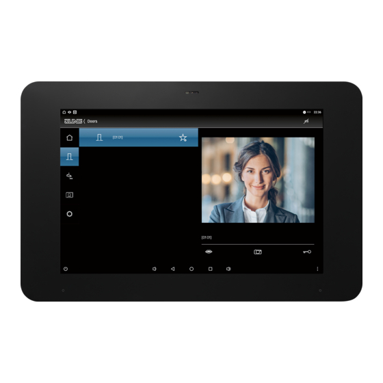
Smart Control 8
Operating instructions manual
Jung Smart Control 8 Operating Instructions Manual
Hide thumbs
1
2
Table Of Contents
3
4
5
6
7
8
9
10
11
12
13
14
15
16
page
of
16
Go
/
16
Contents
Table of Contents
Bookmarks
Table of Contents
Table of Contents
Safety Instructions and Device Components
Safety Instructions
Structure of the Device
Function
Intended Purpose
Product Characteristics
Installation and Electrical Connection
Information for Electrically Skilled Persons
Mounting in Installation Box or Appliance Box
Mounting the Adapter
Connection
Mounting of Smart Control
Commissioning
Switching on
Settings - Overview of the Menu Structure
Opening the Settings
Selecting the Language
Selecting Date and Time
Changing the System Password
Cleaning
Technical Data
Accessories
Warranty
Advertisement
Quick Links
Download this manual
Operating instructions
GB
Smart Control 8
Ref.-no.: SC 0081 U
ALBRECHT JUNG
GMBH & CO. KG
Volmestraße 1
58579 Schalksmühle
GERMANY
Tel. +49 2355 806-0
Fax +49 2355 806-204
kundencenter@jung.de
www.jung.de
0024003500
07/2021
Table of
Contents
Previous
Page
Next
Page
1
2
3
4
5
Advertisement
Table of Contents
Need help?
Do you have a question about the Smart Control 8 and is the answer not in the manual?
Ask a question
Questions and answers
Related Manuals for Jung Smart Control 8
Control Panel Jung Smart Control 10 Product Documentation
(24 pages)
Control Panel Jung FP 701 CT Operating Instructions Manual
Facility-panel (12 pages)
Control Panel Jung SP 9 KNX Operating Instructions Manual
(10 pages)
Control Panel Jung Smart Panel 5.1 KNX Operating Instructions Manual
(6 pages)
Control Panel Jung SP 9 FAPVE Instruction Manual
Smart pilot (9 pages)
This manual is also suitable for:
Sc 0081 u
Table of Contents
Print
Rename the bookmark
Delete bookmark?
Delete from my manuals?
Login
Sign In
OR
Sign in with Facebook
Sign in with Google
Upload manual
Upload from disk
Upload from URL


Need help?
Do you have a question about the Smart Control 8 and is the answer not in the manual?
Questions and answers