
Related Manuals for DEEP SEA ELECTRONICS DSE8620


Summary of Contents for DEEP SEA ELECTRONICS DSE8620
- Page 1 DEEP SEA ELECTRONICS PLC DSE8620 Control Module Operating Manual Document number 057-142 DSE8620 Operating Manual Issue 1...
- Page 2 The DSE logo is a UK registered trademarks of Deep Sea Electronics PLC. Any reference to trademarked product names used within this publication is owned by their respective companies. Deep Sea Electronics Plc reserves the right to change the contents of this document without prior notice. Amendments List...
-
Page 3: Table Of Contents
DSE Model 8620 AMF Controller Operators Manual TABLE OF CONTENTS Section Page BIBLIOGRAPHY ...................7 INSTALLATION INSTRUCTIONS ................. 7 TRAINING GUIDES ..................... 7 MANUALS ........................7 INTRODUCTION ...................8 SPECIFICATIONS..................9 PART NUMBERING ....................9 3.1.1 SHORT NAMES ....................9 TERMINAL SPECIFICATION ..................10 POWER SUPPLY REQUIREMENTS ................ - Page 4 EARTH SYSTEMS ....................51 TYPICAL ARRANGEMENT OF DSENET® ..............52 4.4.1 EARTH SYSTEMS ....................53 DESCRIPTION OF CONTROLS ..............54 DSE8620 AUTOMATIC MAINS FAILURE (AMF) CONTROL MODULE ......54 VIEWING THE INSTRUMENT PAGES ............... 56 5.2.1 STATUS ......................57 5.2.2 ENGINE ......................
- Page 5 DSE Model 8620 AMF Controller Operators Manual 7.1.2 SHUTDOWN / ELECTRICAL TRIP ALARMS............86 7.1.3 CAN ALARMS ....................87 INDICATIONS ......................88 WARNINGS ......................89 HIGH CURRENT WARNING ALARM ................90 SHUTDOWNS......................91 ELECTRICAL TRIPS ....................93 HIGH CURRENT SHUTDOWN / ELECTRICAL TRIP ALARM ........94 7.7.1 IMMEDIATE WARNING ..................
- Page 6 DSE Model 8620 AMF Controller Operators Manual 16.2 PURCHASING ADDITIONAL FIXING CLIPS FROM DSE........118 16.3 PURCHASING ADDITIONAL SEALING GASKET FROM DSE ........ 118 16.4 DSENET EXPANSION MODULES ................ 119 16.5 ETHERNET (LAN) CONNECTION ................ 119 WARRANTY ................... 120 DISPOSAL ..................... 120 18.1 WEEE (WASTE ELECTRICAL AND ELECTRONIC EQUIPMENT) ......
-
Page 7: Bibliography
Installation instructions are supplied with the product in the box and are intended as a ‘quick start’ guide only. DSE PART DESCRIPTION 053-129 DSE8620 Installation Instructions 053-032 DSE2548 LED Expansion Annunciator Installation Instructions 053-033 DSE2130 Input Expansion Installation Instructions 053-034 DSE2157 Output Expansion Installation Instructions 1.2 TRAINING GUIDES... -
Page 8: Introduction
DSE website at www.deepseaplc.com The DSE8620 module has been designed to allow the operator to start and stop the generator, and if required, transfer the load to the generator either manually (via fascia mounted push-buttons) or automatically. -
Page 9: Specifications
At the time of this document production, there have been no revisions to the module hardware. 3.1.1 SHORT NAMES Short name Description DSE8000, All modules in the DSE8000 Series DSE8600,DSE86xx All modules in the DSE8600 sync/load share range DSE8620 DSE8620 module... -
Page 10: Terminal Specification
DSE Model 8620 AMF Controller Operators Manual 3.2 TERMINAL SPECIFICATION Connection type Two part connector. • Male part fitted to module • Female part supplied in module packing case - Screw terminal, rising clamp, no Example showing cable entry and screw internal spring. -
Page 11: Generator Current Sensing
VA RATING OF THE CTS The VA burden of the DSE8620 module on the CTs is 0.5VA. However depending upon the type and length of cabling between the CTs and the DSE8620 module, CTs with a greater VA rating than the module are required. -
Page 12: Ct Polarity
DSE Model 8620 AMF Controller Operators Manual 3.5.2 CT POLARITY Take care to ensure the correct polarity of the CTs. Incorrect CT orientation will lead to negative kW readings when the set is supplying power. Take note that paper stick-on labels on CTs that show the orientation are often incorrectly placed on the CT (!). -
Page 13: Inputs
DSE Model 8620 AMF Controller Operators Manual 3.6 INPUTS 3.6.1 DIGITAL INPUTS Number 11 configurable inputs Arrangement Contact between terminal and ground Low level threshold 2.1V minimum High level threshold 6.6V maximum Maximum input voltage +50V DC with respect to plant supply negative Minimum input voltage -24V DC with respect to plant supply negative Contact wetting current... -
Page 14: Charge Fail Input
DSE Model 8620 AMF Controller Operators Manual Flexible sensor Number Measurement type Resistance measurement by measuring voltage across sensor with a fixed current applied Arrangement Differential resistance measurement input Measurement current 10mA Full scale 480Ω Over range / fail 540Ω Resolution Accuracy ±2% of full scale resistance (±9.6Ω) excluding transducer error... -
Page 15: Outputs
DSE Model 8620 AMF Controller Operators Manual 3.7 OUTPUTS Ten (10) digital outputs are fitted to the DSE8620 controller. Additional outputs are provided for by adding up to ten (10) external relay boards (DSE2157). This allows for up to 80 additional digital outputs. -
Page 16: Outputs E,F,G,H, I ,J & K
DSE Model 8620 AMF Controller Operators Manual Closing coils For continuous closing signals (close signal is present continuously when the breaker is closed), follow the instructions above as for Contactor Coils. For momentary (pulsed) closing signals, use OUTPUT D, the normally open relay: Generator When the DSE module requires the breaker closed, the output energises (closing the internal relay) for the period of the Breaker Close Pulse timer after which the output is de-energised (opening the... -
Page 17: Communication Ports
DSE Model 8620 AMF Controller Operators Manual 3.8 COMMUNICATION PORTS USB Port USB2.0 Device for connection to PC running DSE configuration suite only Max distance 6m (yards) Serial Communication RS232 and RS485 are both fitted but and provide independent operation RS232 Serial port Non –... -
Page 18: Usb Connection
DSE Model 8620 AMF Controller Operators Manual 3.9.2 USB CONNECTION The USB port is provided to give a simple means of connection between a PC and the DSE8600 series controller. Using the DSE Configuration Suite Software, the operator is then able to control the module, starting or stopping the generator, selecting operating modes, etc. -
Page 19: Rs232
DSE Model 8620 AMF Controller Operators Manual 3.9.4 RS232 The RS232 port on the DSE8600 series controller supports the Modbus RTU protocol. The Gencomm register table for the controller is available upon request from the DSE Technical Support Department. RS232 is for short distance communication (max 15m) and is typically used to connect the DSE86xx series controller to a telephone or GSM modem for more remote communications. - Page 20 DSE Model 8620 AMF Controller Operators Manual RECOMMENDED EXTERNAL MODEMS: • Multitech Global Modem – MultiModem ZBA (PSTN) DSE Part Number 020-252 (Contact DSE Sales for details of localisation kits for these modems) • Wavecom Fastrak Supreme GSM modem kit (PSU, Antenna and modem)* DSE Part number 0830-001-01 •...
-
Page 21: Rs485
DSE Model 8620 AMF Controller Operators Manual 3.9.5 RS485 The RS485 port on the DSE8600 series controller supports the Modbus RTU protocol. The DSE Gencomm register table for the controller is available upon request from the DSE Technical Support Department. RS485 is used for point-to-point cable connection of more than one device (maximum 32 devices) and allows for connection to PCs, PLCs and Building Management Systems (to name just a few devices). -
Page 22: Ethernet
DSE Model 8620 AMF Controller Operators Manual 3.9.6 ETHERNET The DSE8620 is fitted with ETHERNET socket for connection to LAN (local area networks) Description Do not connect Do not connect Do not connect Do not connect 3.9.6.1 DIRECT PC CONNECTION Requirements •... - Page 23 NOTE:- This cable can be purchased from any good PC or IT store. 3.9.6.2 CONNECTION TO BASIC ETHERNET Requirements • DSE8620 • Ethernet cable (see below) • Working Ethernet (company or home network) • PC with Ethernet port and Windows Internet Explorer 6 or above, Firefox...
- Page 24 NOTE:- DSE Stock a 2m (2yds) Ethernet Cable – Part number 016-137. Alternatively they can be purchased from any good PC or IT store. 3.9.6.3 CONNECTION TO COMPANY INFRASTRUCTURE ETHERNET Requirements • DSE8620 • Ethernet cable (see below) • Working Ethernet (company or home network) •...
- Page 25 DSE Model 8620 AMF Controller Operators Manual Ethernet cable wiring detail For the advanced Engineer, this cable 10baseT/100baseT has both ends terminated as T568A Connection 1 (T568A) Connection 2 (T568A) (as shown below) or T568B. white/green stripe white/green stripe green solid green solid white/orange stripe white/orange stripe...
- Page 26 DSE Model 8620 AMF Controller Operators Manual Ethernet cable wiring detail For the advanced 10baseT/100baseT Engineer, this cable has both ends Connection 1 (T568A) Connection 2 (T568A) terminated as T568A (as shown below) or white/green stripe white/green stripe T568B. green solid green solid white/orange stripe white/orange stripe...
- Page 27 As modem/routers differ enormously in their configuration, it is not possible for DSE to give a complete guide to their use with the DSE8620. However it is possible to give a description of the requirements in generic terms. For details of how to achieve the connection to your modem/router you are referred to the supplier of your modem/router equipment.
-
Page 28: Dsenet® For Expansion Modules
DSE Model 8620 AMF Controller Operators Manual 3.10 DSENET® FOR EXPANSION MODULES DSENet® is the interconnection cable between the host controller and the expansion module(s) and must not be connect to any device other than DSE equipment designed for connection to the DSENet® Cable type Two core screened twisted pair Cable characteristic impedance... -
Page 29: Sounder
DSE Model 8620 AMF Controller Operators Manual 3.11 SOUNDER DSE8600 Series features an internal sounder to draw attention to warning, shutdown and electrical trip alarms. Sounder level 64db @ 1m 3.11.1 ADDING AN EXTERNAL SOUNDER TO THE APPLICATION Should an external alarm or indicator be required, this can be achieved by using the DSE Configuration Suite PC software to configure an auxiliary output for “Audible Alarm”, and by configuring an auxiliary input for “Alarm Mute”... -
Page 30: Dimensions And Mounting
DSE Model 8620 AMF Controller Operators Manual 3.13 DIMENSIONS AND MOUNTING 3.13.1 DIMENSIONS 240.0mm x 181.1mm x 41.7mm (9.4” x 7.1” x 1.6”) PANEL CUTOUT 220mm x 160mm (8.7” x 6.3”) WEIGHT 0.7kg (1.4lb) -
Page 31: Fixing Clips
DSE Model 8620 AMF Controller Operators Manual 3.13.2 FIXING CLIPS The module is held into the panel fascia using the supplied fixing clips. • Withdraw the fixing clip screw (turn anticlockwise) until only the pointed end is protruding from the clip. •... -
Page 32: Cable Tie Fixing Points
DSE Model 8620 AMF Controller Operators Manual 3.13.3 CABLE TIE FIXING POINTS Integral cable tie fixing points are included on the rear of the module’s case to aid wiring. This additionally provides strain relief to the cable loom by removing the weight of the loom from the screw connectors, thus reducing the chance of future connection failures. -
Page 33: Applicable Standards
62 – time delay stopping or opening relay 63 – pressure switch 74– alarm relay 81 – frequency relay 86 – lockout relay In line with our policy of continual development, Deep Sea Electronics, reserve the right to change specification without notice. -
Page 34: Enclosure Classifications
DSE Model 8620 AMF Controller Operators Manual 3.14.1 ENCLOSURE CLASSIFICATIONS IP CLASSIFICATIONS 8600 series specification under BS EN 60529 Degrees of protection provided by enclosures IP65 (Front of module when module is installed into the control panel with the optional sealing gasket). IP42 (front of module when module is installed into the control panel WITHOUT being sealed to the panel) First Digit Second Digit... -
Page 35: Nema Classifications
DSE Model 8620 AMF Controller Operators Manual 3.14.2 NEMA CLASSIFICATIONS 8600 series NEMA Rating (Approximate) 12 (Front of module when module is installed into the control panel with the optional sealing gasket). 2 (front of module when module is installed into the control panel WITHOUT being sealed to the panel) NOTE: - There is no direct equivalence between IP / NEMA ratings. -
Page 36: Installation
DSE Model 8620 AMF Controller Operators Manual 4 INSTALLATION The DSE8xxx Series module is designed to be mounted on the panel fascia. For dimension and mounting details, see the section entitled Specification, Dimension and mounting elsewhere in this document. 4.1 TERMINAL DESCRIPTION To aid user connection, icons are used on the rear of the module to help identify terminal functions. -
Page 37: Dc Supply, Fuel And Start Outputs, Outputs E-J
DSE Model 8620 AMF Controller Operators Manual 4.1.1 DC SUPPLY, FUEL AND START OUTPUTS, OUTPUTS E-J DESCRIPTION CABLE NOTES SIZE DC Plant Supply Input 2.5mm² (Negative) AWG 13 (Recommended Maximum Fuse 15A anti-surge) DC Plant Supply Input 2.5 mm² Supplies the module (2A anti-surge requirement) and (Positive) AWG 13 Output relays E,F,G &... -
Page 38: Analogue Sensor
DSE Model 8620 AMF Controller Operators Manual 4.1.2 ANALOGUE SENSOR DESCRIPTION CABLE NOTES SIZE 0.5mm² Sensor Common Return Return feed for sensors* AWG 20 0.5mm² Oil Pressure Input Connect to Oil pressure sensor AWG 20 0.5mm² Coolant Temperature Input Connect to Coolant Temperature sensor AWG 20 0.5mm²... -
Page 39: Magnetic Pickup, Can And Expansion
DSE Model 8620 AMF Controller Operators Manual 4.1.3 MAGNETIC PICKUP, CAN AND EXPANSION DESCRIPTION CABLE NOTES SIZE 0.5mm² Magnetic pickup Positive Connect to Magnetic Pickup device AWG 20 0.5mm² Magnetic pickup Negative Connect to Magnetic Pickup device AWG 20 Magnetic pickup screen Shield Connect to ground at one end only 0.5mm²... -
Page 40: V1 Load Switching And Generator Voltage Sensing
DSE Model 8620 AMF Controller Operators Manual 4.1.4 V1 LOAD SWITCHING AND GENERATOR VOLTAGE SENSING DESCRIPTION CABLE NOTES SIZE 1.0mm Normally configured to control mains contactor coil Output relay C AWG 18 (Recommend 10A fuse) 1.0mm Output relay C Normally configured to control mains contactor coil AWG 18 1.0mm Normally configured to control generator contactor coil... -
Page 41: Generator Current Transformers
NOTE:- The DSE8620 module has a burden of 0.5VA on the CT. Ensure the CT is rated for the burden of the DSE 8620 controller, the cable length being used and any other equipment sharing the CT. - Page 42 DSE Model 8620 AMF Controller Operators Manual CT CONNECTIONS or K is the primary of the CT that ‘points’ towards the GENERATOR or L is the primary of the CT that ‘points’ towards the LOAD s1 is the secondary of the CT that connects to the DSE Module’s input for the CT measuring (I1,I2,I3) s2 is the secondary of the CT that should be commoned with the s2 connections of all the other CTs and connected to the CT common terminal of the DSE8600 series modules.
-
Page 43: Configurable Digital Inputs
Typically, they extend USB up to 50m (yards). The supply and support of this type of equipment is outside the scope of Deep Sea Electronics PLC. CAUTION!: Care must be taken not to overload the PCs USB system by connecting more than the recommended number of USB devices to the PC. -
Page 44: Rs485 Connector
DSE Model 8620 AMF Controller Operators Manual 4.1.10 RS485 CONNECTOR PIN No NOTES Two core screened twisted pair cable. 120Ω impedance suitable for RS485 use. Recommended cable type - Belden 9841 Max distance 1200m (1.2km) when using Belden 9841 or direct equivalent. Location of RS485 connector Location of RS232 connector... -
Page 45: Typical Wiring Diagrams
DSE Model 8620 AMF Controller Operators Manual 4.2 TYPICAL WIRING DIAGRAMS As every system has different requirements, these diagrams show only a TYPICAL system and do not intend to show a complete system. Genset manufacturers and panel builders may use these diagrams as a starting point; however, you are referred to the completed system diagram provided by your system manufacturer for complete wiring detail. -
Page 46: Phase, 4 Wire With Restricted Earth Fault Protection
DSE Model 8620 AMF Controller Operators Manual 4.2.1 3 PHASE, 4 WIRE WITH RESTRICTED EARTH FAULT PROTECTION NOTE:- Earthing the neutral conductor ‘before’ the neutral CT allows the module to read earth faults ‘after’ the CT only (Restricted to load / downstream of the CT) Earthing the neutral conductor ‘after’... -
Page 47: Alternative Topologies
DSE Model 8620 AMF Controller Operators Manual 4.3 ALTERNATIVE TOPOLOGIES The 8000 controller is factory configured to connect to a 3 phase, 4 wire Star connected alternator. This section details connections for alternative AC topologies. Ensure to configure the 8000 series controller to suit the required topology. -
Page 48: Single Phase With Restricted Earth Fault
DSE Model 8620 AMF Controller Operators Manual 4.3.2 SINGLE PHASE WITH RESTRICTED EARTH FAULT NOTE:- Earthing the neutral conductor ‘before’ the neutral CT allows the module to read earth faults ‘after’ the CT only (Restricted to load / downstream of the CT) Earthing the neutral conductor ‘after’... -
Page 49: Phase (L1 & L2) 3 Wire With Restricted Earth Fault
DSE Model 8620 AMF Controller Operators Manual 4.3.4 2 PHASE (L1 & L2) 3 WIRE WITH RESTRICTED EARTH FAULT NOTE:- Earthing the neutral conductor ‘before’ the neutral CT allows the module to read earth faults ‘after’ the CT only (Restricted to load / downstream of the CT) Earthing the neutral conductor ‘after’... -
Page 50: Phase (L1 & L3) 3 Wire With Restricted Earth Fault
DSE Model 8620 AMF Controller Operators Manual 4.3.6 2 PHASE (L1 & L3) 3 WIRE WITH RESTRICTED EARTH FAULT NOTE:- Earthing the neutral conductor ‘before’ the neutral CT allows the module to read earth faults ‘after’ the CT only (Restricted to load / downstream of the CT) Earthing the neutral conductor ‘after’... -
Page 51: Phase 4 Wire With Unrestricted Earth Fault Measuring
DSE Model 8620 AMF Controller Operators Manual 4.3.8 3 PHASE 4 WIRE WITH UNRESTRICTED EARTH FAULT MEASURING NOTE:- Unrestricted Earth Fault Protection detects earth faults in the load and in the generator. Be sure to measure the natural earth fault of the site before deciding upon an earth fault alarm trip level. -
Page 52: Typical Arrangement Of Dsenet
DSE Model 8620 AMF Controller Operators Manual 4.4 TYPICAL ARRANGEMENT OF DSENET® Twenty (20) devices can be connected to the DSENet®, made up of the following devices : Device Max number supported DSE2130 Input Expansion DSE2157 Output Expansion DSE2548 LED Expansion For part numbers of the expansion modules and their documentation, see section entitled DSENet Expansion Modules elsewhere in this manual. -
Page 53: Earth Systems
DSE Model 8620 AMF Controller Operators Manual 4.4.1 EARTH SYSTEMS 4.4.1.1 Negative Earth The typical wiring diagrams located within this document show connections for a negative earth system (the battery negative connects to Earth) 4.4.1.2 Positive Earth When using a DSE module with a Positive Earth System (the battery positive connects to Earth), the following points must be followed: •... -
Page 54: Description Of Controls
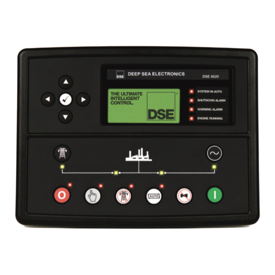
DSE Model 8620 AMF Controller Operators Manual 5 DESCRIPTION OF CONTROLS The following section details the function and meaning of the various controls on the module. 5.1 DSE8620 AUTOMATIC MAINS FAILURE (AMF) CONTROL MODULE Main status and Four configurable instrumentation display... - Page 55 DSE Model 8620 AMF Controller Operators Manual Mains Available LED. On when the mains is within limits and able to take load. Generator Available LED. On when the generator is within limits and able to take load. Close Mains LED. Close Bus LED.
-
Page 56: Viewing The Instrument
DSE Model 8620 AMF Controller Operators Manual 5.2 VIEWING THE INSTRUMENT PAGES It is possible to scroll to display the different pages of information by repeatedly operating the next / previous page buttons If you want to view one of the instrument pages towards the end of the list, it may be quicker to scroll left through... -
Page 57: Status
DSE Model 8620 AMF Controller Operators Manual 5.2.1 STATUS This is the ‘home’ page, the page that is displayed when no other page has been selected, and the page that is automatically displayed after a period of inactivity (LCD Page Timer) of the module control buttons. -
Page 58: Engine
DSE Model 8620 AMF Controller Operators Manual 5.2.2 ENGINE Contains instrumentation gathered about the engine itself, some of which may be obtained using the CAN or other electronic engine link. • Engine Speed • Oil Pressure • Coolant Temperature • Engine Battery Volts •... -
Page 59: Generator
DSE Model 8620 AMF Controller Operators Manual 5.2.3 GENERATOR Contains electrical values of the generator (alternator), measured or derived from the module’s voltage and current inputs. • Generator Voltage (ph-N) • Generator Voltage (ph-ph) • Generator Frequency • Generator Current •... -
Page 60: Rs232 Serial Port
DSE Model 8620 AMF Controller Operators Manual 5.2.1 RS232 SERIAL PORT This section is included to give information about the RS232 serial port and external modem (if connected). The items displayed on this page will change depending upon configuration of the module. You are referred to your system supplier for further details. - Page 61 DSE Model 8620 AMF Controller Operators Manual Example 1 continued – Modem diagnostics Modem diagnostic screens are included; press when viewing the RS232 Serial Port instrument to cycle the available screens. If you are experiencing modem communication problems, this information will aid troubleshooting. Shows the state of the modem communication lines.
- Page 62 DSE Model 8620 AMF Controller Operators Manual In case of communication failure between the modem and DSE8600 series module, the modem is automatically reset and initialisation is attempted once more: In the case of a module that is unable to communicate with the modem, the display will continuously cycle between ‘Modem Reset’...
-
Page 63: Rs485 Serial Port
DSE Model 8620 AMF Controller Operators Manual 5.2.1 RS485 SERIAL PORT This section is included to give information about the currently selected serial port and external modem (if connected). The items displayed on this page will change depending upon configuration of the module. You are referred to your system supplier for further details. -
Page 64: About
DSE Model 8620 AMF Controller Operators Manual Typical requests (using Pseudo code) : reads register (hex) 0405 as a single register (battery volts) BatteryVoltage=ReadRegister(10,0405,1) from slave address 10. : Puts the module into AUTO mode by writing to (hex) WriteRegister(10,1008,2,35701, 65535-35701) register 1008, the values 35701 (auto mode) and register 1009 the value 65535-35701 (the bitwise opposite of auto mode) : reads (hex) 0306 and looks at bit 13 (shutdown alarm... - Page 65 DSE Model 8620 AMF Controller Operators Manual Network Network Network Network Unique setting for each module MAC address MAC address MAC address MAC address E8.A4.C1.0.A.C2 E8.A4.C1.0.A.C2 E8.A4.C1.0.A.C2 E8.A4.C1.0.A.C2 DHCP DHCP DHCP DHCP HOST HOST HOST HOST DOMAIN DOMAIN DOMAIN DOMAIN Vendor Vendor Vendor...
-
Page 66: Can Error Messages
DSE Model 8620 AMF Controller Operators Manual Time remaining xxxx h xx m Press down to view the next page. Data Logging Memory remaining Memory space remaining, this depends what size memory drive is fitted (Max xxxx 16Gb) or allocated internal (2Mb) memory left available. -
Page 67: Viewing The Event Log
DSE Model 8620 AMF Controller Operators Manual 5.3 VIEWING THE EVENT LOG The DSE8600 series modules maintain a log of past alarms and/or selected status changes. The log size has been increased in the module over past module updates and is always subject to change. -
Page 68: User Configurable Indicators
DSE Model 8620 AMF Controller Operators Manual 5.4 USER CONFIGURABLE INDICATORS These LEDs can be configured by the user to indicate any one of 100+ different functions based around the following:- • Indications - Monitoring of a digital input and indicating associated functioning user’s equipment - Such as Battery Charger On or Louvres Open, etc. -
Page 69: Operation
6 OPERATION 6.1 CONTROL Control of the DSE8620 module is via push buttons mounted on the front of the module with STOP/RESET, MANUAL, TEST, AUTO, ALARM MUTE and START functions. For normal operation, these are the only controls which need to be operated. The smaller push buttons are used to access further information such as mains voltage or to change the state of the load switching devices when in manual mode. -
Page 70: Control Push-Buttons
DSE Model 8620 AMF Controller Operators Manual 6.2 CONTROL PUSH-BUTTONS STOP/RESET This push-button places the module into its Stop/reset mode. This will clear any alarm conditions for which the triggering criteria have been removed. If the engine is running and this push-button is operated, the module will automatically instruct the generator contactor/breaker to unload the generator. - Page 71 DSE Model 8620 AMF Controller Operators Manual Test This button places the module into its ‘Test’ mode. This allows an on load test of the generator. Once in Test mode the module will respond to the start button, start the engine, and run on load.
-
Page 72: Dummy Load / Load Shedding Control
DSE Model 8620 AMF Controller Operators Manual 6.3 DUMMY LOAD / LOAD SHEDDING CONTROL This feature may be enabled by the system designer to ensure the loading on the generator is kept to a nominal amount. If the load is low, ‘dummy loads’ (typically static load banks) can be introduced to ensure the engine is not too lightly loaded. -
Page 73: Stop Mode
DSE Model 8620 AMF Controller Operators Manual 6.4 STOP MODE STOP mode is activated by pressing the button. In STOP mode, the module will remove the generator from load (if necessary) before stopping the engine if it is already running. If the engine does not stop when requested, the FAIL TO STOP alarm is activated (subject to the setting of the Fail to Stop timer). -
Page 74: Ecu Override
DSE Model 8620 AMF Controller Operators Manual 6.4.1 ECU OVERRIDE NOTE:- ECU Override function is only applicable when the controller is configured for a CAN engine. NOTE:- Depending upon system design, the ECU may be powered or unpowered when the module is in STOP mode. -
Page 75: Automatic Operation
DSE Model 8620 AMF Controller Operators Manual 6.5 AUTOMATIC OPERATION 6.5.1 MAINS FAILURE This mode of operation is used to ensure continuity of supply to critical loads during a mains failure condition. This is the normal mode of operation when installed on a standby generator. NOTE: If a digital input configured to panel lock is active, changing module modes will not be possible. -
Page 76: Engine Running
DSE Model 8620 AMF Controller Operators Manual After the starter motor has disengaged, the Safety On timer is activated, allowing Oil Pressure, High Engine Temperature, Under-speed, Charge Fail and any delayed Auxiliary fault inputs to stabilise without triggering the fault. 6.5.1 ENGINE RUNNING Once the engine is running, the Warm Up timer, if selected, begins, allowing the engine to stabilise... -
Page 77: Remote Start In Island Mode
DSE Model 8620 AMF Controller Operators Manual 6.5.2 REMOTE START IN ISLAND MODE This mode of operation is used to start the set in response to an external start requirement from another device. It may also be used to provide continuity of supply during expected black out events. NOTE:- If a digital input configured to panel lock is active, changing module modes will not be possible. - Page 78 DSE Model 8620 AMF Controller Operators Manual After the starter motor has disengaged, the Safety On timer is activated, allowing Oil Pressure, High Engine Temperature, Under-speed, Charge Fail and any delayed Auxiliary fault inputs to stabilise without triggering the fault. Once the engine is running, the Warm Up timer, if selected is initiated, allowing the engine to stabilise before accepting the load.
-
Page 79: Remote Start On Load
DSE Model 8620 AMF Controller Operators Manual 6.5.3 REMOTE START ON LOAD This mode of operation is used to start the set in response to rising load levels on the mains supply (if configured). NOTE: - If a digital input configured to panel lock is active, changing module modes will not be possible. - Page 80 DSE Model 8620 AMF Controller Operators Manual After the starter motor has disengaged, the Safety On timer is activated, allowing Oil Pressure, High Engine Temperature, Under-speed, Charge Fail and any delayed Auxiliary fault inputs to stabilise without triggering the fault. Once the engine is running, the Warm Up timer, if selected is initiated, allowing the engine to stabilise before accepting the load.
-
Page 81: Manual Operation
DSE Model 8620 AMF Controller Operators Manual 6.6 MANUAL OPERATION Manual mode is used to allow the operator to control the operation of the generator, and to provide fault finding and diagnostic testing of the various operations normally performed during Automatic mode operation. - Page 82 DSE Model 8620 AMF Controller Operators Manual The generator will run off load unless: 1. The mains supply fails, 2. A Remote Start on load signal is applied, or an on-load run is configured in the scheduler. 3. The Close Generator button is pressed. If any of the above signals are received, the generator is synchronised and paralleled with the mains supply (if available).
-
Page 83: Test Operation
DSE Model 8620 AMF Controller Operators Manual 6.7 TEST OPERATION Test operation is used to perform a full on load test sequence to allow for diagnosis of faults. Alternatively, it may also be used to provide continuity of supply during expected black out events, peak lopping or peak shaving during high tariff periods. - Page 84 DSE Model 8620 AMF Controller Operators Manual Once the engine is running, the Warm Up timer, if selected is initiated, allowing the engine to stabilise before accepting the load. After the Warm-up timer has expired then the module will transfer the load from the mains supply to the generator output.
-
Page 85: Protections
DSE Model 8620 AMF Controller Operators Manual 7 PROTECTIONS When an alarm is present, the Audible Alarm will sound and the Common alarm LED if configured will illuminate. The audible alarm can be silenced by pressing the Mute button The LCD display will jump from the ‘Information page’ to display the Alarm Page Number of present alarms. -
Page 86: Protections Disabled
DSE Model 8620 AMF Controller Operators Manual 7.1 PROTECTIONS DISABLED User configuration is possible to prevent Shutdown / Electrical Trip alarms from stopping the engine. Under such conditions, Protections Disabled will appear on the module display to inform the operator of this status. -
Page 87: Can Alarms
DSE Model 8620 AMF Controller Operators Manual 7.1.3 CAN ALARMS NOTE:- Please refer to the engine manufacturer’s documentation for Can error message information. CAN alarms are messages sent from the CAN ECU to the DSE controller and displayed as follows in the below tables. -
Page 88: Indications
DSE Model 8620 AMF Controller Operators Manual 7.2 INDICATIONS Indications are non-critical and often status conditions. They do not appear on the LCD of the module as a text message. However, an output or LED indicator can be configured to draw the operator’s attention to the event. -
Page 89: Warnings
DSE Model 8620 AMF Controller Operators Manual 7.3 WARNINGS Warnings are non-critical alarm conditions and do not affect the operation of the generator system, they serve to draw the operators attention to an undesirable condition. Example Alarm Charge Failure Warning In the event of an alarm the LCD will jump to the alarms page, and scroll through all active warnings and shutdowns. -
Page 90: High Current Warning Alarm
DSE Model 8620 AMF Controller Operators Manual NOT REACHED frequency. The generator will not take load when the alarm is present after the safety timer. PROTECTIONS DISABLED Shutdown and electrical trip alarms can be disabled by user configuration. In this case, Protections Disabled will appear on the module display;... -
Page 91: Shutdowns
DSE Model 8620 AMF Controller Operators Manual 7.5 SHUTDOWNS NOTE:- Shutdown and Electrical Trip alarms can be disabled by user configuration. See the section entitled Protections Disabled elsewhere in this document. Shutdowns are latching alarms and stop the Generator. Clear the alarm and remove the fault then press Stop/Reset to reset the module. - Page 92 DSE Model 8620 AMF Controller Operators Manual UNDERSPEED The engine speed has fallen below the pre-set trip after the Safety On timer has expired. Display Reason GENERATOR OVER FREQUENCY The generator output frequency has risen above the preset level GENERATOR UNDER FREQUENCY The generator output frequency has fallen below the preset level GENERATOR OVER VOLTAGE The generator output voltage has risen above the preset level...
-
Page 93: Electrical Trips
DSE Model 8620 AMF Controller Operators Manual 7.6 ELECTRICAL TRIPS NOTE:- Shutdown and Electrical Trip alarms can be disabled by user configuration. See the section entitled Protections Disabled elsewhere in this document. Electrical trips are latching and stop the Generator but in a controlled manner. On initiation of the electrical trip condition the module will de-energise the ‘Close Generator’... -
Page 94: High Current Shutdown / Electrical Trip Alarm
DSE Model 8620 AMF Controller Operators Manual GENERATOR UNDER VOLTAGE The generator output voltage has fallen below the preset level INSUFFICIENT CAPACITY If the module is configured for Mains CT and the load levels are so high that the generator is unable to supply enough load to maintain the configured mains level, insufficient capacity will be displayed and the COMMON ALARM LED will flash. - Page 95 DSE Model 8620 AMF Controller Operators Manual Factory settings for the IDMT Alarm when used on a brushless alternator are as follows (screen capture from the DSE Configuration Suite PC software : (Trip setting value) (time multiplier) These settings provide for normal running of the generator up to 100% full load. If full load is surpassed, the Immediate Warning alarm is triggered, the set continues to run.
-
Page 96: Earth Fault Shutdown / Electrical Trip Alarm
DSE Configuration Suite software. 7.9 SHORT CIRCUIT ALARM If the Short Circuit alarm is enabled, the DSE8620 controller begins following the IDMT ‘curve’. If the Trip is surpassed for an excess amount of time the Alarm triggers (Shutdown or Electrical trip as selected in Action). -
Page 97: Rocof / Vector Shift
For details on activating and configuring the ROCOF/Vector shift protection you are referred to the DSE8620 software manual. 7.10.1 MAINS DECOUPLING TEST MODE To aid the testing of the mains decoupling features in the controller, a special test mode is included. -
Page 98: Scheduler
DSE Model 8620 AMF Controller Operators Manual 8 SCHEDULER DSE8600 Series contains an inbuilt exercise run scheduler, capable of automatically starting and stopping the set. Up to 16 scheduled start/stop sequences can be configured to repeat on a 7-day or 28-day cycle. -
Page 99: Synchroscope Operation
DSE Model 8620 AMF Controller Operators Manual 9 SYNCHROSCOPE OPERATION Initial stage of Synchronising display will only show the difference between the Mains Supply and the V +0.2 Hz +2.9 Generator Output. Here the display is showing a frequency mismatch of +2.9Hz - The genset frequency is too high (indicated by the arrow) and should be reduced. -
Page 100: Commissioning
DSE Model 8620 AMF Controller Operators Manual 10 COMMISSIONING 10.1 COMMISSIONING SCREENS Commissioning screens are available to both aid the commissioning process and also to give additional information about the synchronising and load sharing process. These screens can be enabled and disabled in the module’s display editor. 10.1.1 SCREEN 1 Average L-L Voltage and total kW L –... -
Page 101: Front Panel Configuration
DSE Model 8620 AMF Controller Operators Manual 11 FRONT PANEL CONFIGURATION This configuration mode allows the operator limited customising of the way the module operates. Use the module’s navigation buttons to traverse the menu and make value changes to the parameters: Increase value / next item Next page Previous page... -
Page 102: Accessing The Main Front Panel Configuration Editor
DSE Model 8620 AMF Controller Operators Manual 11.1 ACCESSING THE MAIN FRONT PANEL CONFIGURATION EDITOR Ensure the engine is at rest and the module is in STOP mode by pressing the Stop/Reset button. Press the Stop/Reset and Info buttons simultaneously. If a module security PIN has been set, the PIN number request is then shown : Press , the first ‘#’... -
Page 103: Editing A Parameter
DSE Model 8620 AMF Controller Operators Manual 11.1.1 EDITING A PARAMETER Enter the editor as described above. Press the (left) or (right) buttons to cycle to the section you wish to view/change. Press the (up or down) buttons to select the parameter you wish to view/change within the currently selected section. -
Page 104: Adjustable Parameters
DSE Model 8620 AMF Controller Operators Manual 11.2 ADJUSTABLE PARAMETERS Front Panel Configuration Editor. For descriptions of the parameters, you are referred to The DSE8600 series Configuration Suite Manual, DSE Part 057-119. Section Parameter as shown on display Values Contrast Display Language English, others. -
Page 105: Accessing The 'Running' Configuration Editor
DSE Model 8620 AMF Controller Operators Manual Schedule Time & Date Selection (1-16) Press to begin editing then when selecting the different parameters in the scheduler. 11.3 ACCESSING THE ‘RUNNING’ CONFIGURATION EDITOR The ‘running’ editor can be entered while the engine is running. All protections remain active if the engine is running while the running editor is entered. -
Page 106: Fault Finding
DSE Model 8620 AMF Controller Operators Manual 12 FAULT FINDING SYMPTOM POSSIBLE REMEDY Unit is inoperative Check the battery and wiring to the unit. Check the DC supply. Check the DC fuse. Unit shuts down Check DC supply voltage is not above 35 Volts or below 9 Volts when the module is operating. -
Page 107: Earth Fault Tripping Curves
12.1.1 EARTH FAULT TRIPPING CURVES NOTE: DSE Factory setting is time multiplier (K) = 0.4 DSE8620 Operating Manual Issue 1... -
Page 108: Short Circuit Tripping Curves
DSE Model 8620 Main Control and ATS Operators Manual 12.1.2 SHORT CIRCUIT TRIPPING CURVES NOTE: DSE Factory setting is time multiplier (K) = 0.01 Trip time (mS) Multiple of trip point setting... -
Page 109: Communications Option
DSE Model 8620 Main Control and ATS Operators Manual 12.2 COMMUNICATIONS OPTION 12.2.1 DESCRIPTION The 86xx series configuration software allows the 8620 controller to communicate with a PC. The computer can be connected to the module either directly, via a modem (RS232) or via an RS485 link. The operator is then able to remotely control the module, starting or stopping the generator, selecting operating modes, etc. -
Page 110: Modbus
All supported data can be read and written as specified in the register table (documentation is available from Deep Sea Electronics Plc.). When the 8620 Module receives a query it will respond by either supplying the requested register data or performing the requested action. - Page 111 DSE Model 8620 Main Control and ATS Operators Manual separate excitation A device that connects a circuit, such as the shunt field of a synchronous device converter, to a source of separate excitation during the starting sequence. A device that operates on a predetermined value of power flow in a given directional power direction such as reverse power flow resulting from the motoring of a relay...
- Page 112 DSE Model 8620 Main Control and ATS Operators Manual Device Description A device that is used to close and interrupt an ac power circuit under normal 52 ac circuit breaker conditions or to interrupt this circuit under fault or emergency conditions. turning gear A device electrically operated, controlled, or monitored that functions to engaging device...
-
Page 113: Commissioning
DSE Model 8620 Main Control and ATS Operators Manual 13 COMMISSIONING 13.1.1 PRE-COMMISSIONING Before the system is started, it is recommended that the following checks are made:- 10.1. The unit is adequately cooled and all the wiring to the module is of a standard and rating compatible with the system. - Page 114 DSE Model 8620 Main Control and ATS Operators Manual Website : www.deepseaplc.com...
-
Page 115: Fault Finding
DSE Model 8620 Main Control and ATS Operators Manual 14 FAULT FINDING SYMPTOM POSSIBLE REMEDY Unit is inoperative Check the battery and wiring to the unit. Check the DC supply. Check the DC fuse. Read/Write configuration does not operate Unit shuts down Check DC supply voltage is not above 35 Volts or below 9 Volts Check the operating temperature is not above 70°... - Page 116 DSE Model 8620 Main Control and ATS Operators Manual SYMPTOM POSSIBLE REMEDY Incorrect reading on Engine Check engine is operating correctly. Check sensor and wiring paying particular gauges attention to the wiring to terminal 47 (refer to appendix). Check that sensor is compatible with the 8600 series module and that the module configuration is Fail to stop alarm when engine is suited to the sensor.
-
Page 117: Dse 4 Steps To Successful Synchronising
DSE Model 8620 Main Control and ATS Operators Manual 15 DSE 4 STEPS TO SUCCESSFUL SYNCHRONISING Synchronising and load sharing is often considered to be a complex subject. In fact, it is very simple when broken down into smaller steps. After following the Commissioning section of this manual, the 4 Steps must be followed before any parallel operation is attempted. -
Page 118: Maintenance, Spares, Repair And Servicing
16.1 PURCHASING ADDITIONAL CONNECTOR PLUGS FROM DSE If you require additional plugs from DSE, please contact our Sales department using the part numbers below. 16.1.1.1 Pack of plugs Module type Plug Pack Part Number DSE8620 100-400-86 16.1.1.2 Individual plugs 8600 series terminal designation Plug description Part No. -
Page 119: Dsenet Expansion Modules
DSE8600 series controller. 16.5 ETHERNET (LAN) CONNECTION NOTE: - DSE860 and DSE865 cannot be used with the DSE8620 although this module does have its own dedicated Ethernet port. (See beginning of manual for details) -
Page 120: Warranty
DSE Model 8620 Main Control and ATS Operators Manual 17 WARRANTY DSE provides limited warranty to the equipment purchaser at the point of sale. For full details of any applicable warranty, you are referred to your original equipment supplier (OEM). 18 DISPOSAL 18.1 WEEE (WASTE ELECTRICAL AND ELECTRONIC EQUIPMENT) Directive 2002/96/EC... - Page 121 DSE Model 8620 Main Control and ATS Operators Manual This page is intentionally left blank...
- Page 122 DSE Model 8620 Main Control and ATS Operators Manual This page is intentionally left blank.
Need help?
Do you have a question about the DSE8620 and is the answer not in the manual?
Questions and answers