Seca 644 Service Manual
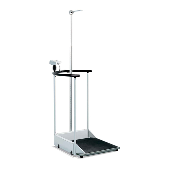
Electronic scale with standing aid, easily manoeuvrable, pre-tara function with three adjustable values, turnable display and operating housing
Hide thumbs
Also See for 644:
- Instruction manual and guarantee (409 pages) ,
- Service manual (74 pages) ,
- Manual (59 pages)
Advertisement
Quick Links
Variants:
6441321004
6441321104
6441321134
6457021008
6457021098
6457021198
6457021228
6457021243
6457021288
Content:
Short description display module
Short description DMS module
Description of faults
Function diagram
Description of calibration
PC configuration program
Cableplan
Replacement
Spare parts
Manual number:
17-05-01-305-g
Service Manual
for seca 644/645
Description:
Electronic scale with standing aid, easily manoeuvrable. Pre-tara function with
three adjustable values. Turnable display and operating housing.
Service Manual Number
17-05-01-305-g
Valid as of:
30-34-00-618 a
30-34-00-645 b
30-34-00-588 d
25-02-02-209 a
30-34-00-603
30-34-00-672 b
08-02-06-022 c
30-34-00-678 a
30-34-00-679 f
06.07.2011
Advertisement

Related Manuals for Seca 644


Summary of Contents for Seca 644
- Page 1 Service Manual Variants: for seca 644/645 6441321004 6441321104 Service Manual Number 6441321134 17-05-01-305-g Valid as of: 06.07.2011 6457021008 6457021098 6457021198 Description: 6457021228 Electronic scale with standing aid, easily manoeuvrable. Pre-tara function with 6457021243 three adjustable values. Turnable display and operating housing.
- Page 2 Brief description of the display module Introduction The display modules belong to the family of seca electronic modules and are used to display a weight measured with a suitable module and transferred via the SeSAM bus (Seca’s Serial Autoconfiguring Multicontroller bus). Furthermore, the display modules accommodate the operating elements and can process the weight (hold, tare, etc.).
- Page 3 Power supply Power supply is provided via the SeSAM bus. Operation With the exception of a start button that might be available, the connected buttons can be configured as required for the particular model. These buttons can be pressed just lightly or longer (longer than 1.5s).
- Page 4 Recalibration In order to compensate for linear measuring errors of the scale, which can, for instance, occur as a result of the different forces of gravity at different geographical points, the module has a recalibration function. To initiate the function, another button must be pressed when the scale is started. The verification counter is then displayed which is incremented whenever the scale is recalibrated.
- Page 5 Technical data Supply voltage: 2.7V - 3V and 2.7V - 15V (via SeSAM bus) Supply current: typ. 0.5mA + power supply for backlighting (typ. 100mA) Quiescent current: typ. 2µA Operating temperature: approx. 0°C to 50°C Storage temperature: -10°C to 60°C Dimensions: 74mm x 50mm x 23mm small display...
- Page 6 EEPROM is integrated which is used to configure the module. A connection to the SeSAM bus (Seca’s Serial Autoconfiguring Multicontroller bus) is provided via which the scale can be calibrated and additional modules can be connected.
- Page 7 Service manual Description of the electronics Display (only DMS low-end module and SLC highend) Whenever eight new measured values are available, i.e. approx. every 0.8 s, the weight is displayed. The display is an LCD which is controlled by duplex operation. A maximum of five digits as well as a few special characters can be displayed.
- Page 8 Service manual Description of the electronics If the start button is directly connected to this interrupt input, a button is obtained which is only active when the scale is switched off. It can be fitted under the platform, for instance, so that the scale is started by briefly stepping on it.
- Page 9 Service manual Description of the electronics Time base From the quartz’s 4.19MHz a time base is derived which controls all timed processes in the scale. These are, for instance, various timeouts and the on-time. After expiry of the on-time, the supply voltage for the analog part, for voltage measurement and for the EEPROM is switched off.
- Page 10 Service manual Description of the electronics Technical data Supply voltage: Load cell voltage + 0.5 V to 15 V Supply current: approximate load cell current Zero-signal current: typ. 2µA Operating temperature: approx. 0°C to 50°C Storage temperature: -10°C to 60°C 05.08.03 /Jensen / Rei 34-34-00-645 b...
- Page 11 Service manual Description of faults Please refer to the operating instructions to make sure that scale malfunctions are not caused by operation faults. Should any faults occur, the following table will help you to identify the cause of the fault. Fault description Possible cause Remedy...
- Page 12 Service manual Description of faults Fault description Possible cause Remedy Er:X:14 Fault in the kg value Wrong coefficients in the module’s ROM, reprogram and readjust the calculation scale Er:X:15 Recalibration fault Reference weight outside the permitted range or operating fault ...
- Page 14 General: General: Seca scales with modular electronics are fitted with a software-controlled calibration device that is operated using the existing controls. This device can be used to recalibrate the scales or to set the scales to different GAL values. During development of the calibration device, special attention was paid to the following requirements: •...
- Page 15 Vogel & Halke File: 00603_e1.doc seca Created on: 30.06.1998 Printed on: 07.07.1999 Holger Panier / SE Pressing the kg/lbs key for less than 1.5 seconds causes the weight shown on the display to be increased or decreased by 10 g (depending on the mode currently selected). As the resolution of the display is lower, the displayed value will not necessarily be increased or decreased each time the kg/lbs key is pressed.
- Page 16 Vogel & Halke File: 00603_e1.doc seca Created on: 30.06.1998 Printed on: 07.07.1999 Holger Panier / SE Summary of a typical recalibration sequence: Summary of a typical recalibration sequence: Action carried out by the user Result The scales are switched off.
- Page 17 1 (2) PC configuration program page Instructions for PC-based configuration PC-based configuration is used for diagnosis or recalibration of all seca scales with modular electronics. The following equipment is required: • PC with serial interface (RS -232) • seca software 'SERVA”...
- Page 18 2 (2) PC configuration program page Standard case Connection to the existing display unit port. The display can instead be connected to the second modular socket of the service module. DMS module with integrated display 08-06-18-082 If there is no modular socket on the back of the PCB, retrofit one.
- Page 20 Service Manual Replacement instructions seca 644, 645 The references to pages and items relate to the replacement instructions drawing, Pages 5 – 14. The power supply unit must not be connected. We urgently recommend that you remove the rechargeable battery pack before starting any work on the unit: Remove the 2 screws (Page 11, Item 11.1) and the battery cover (Item 11.2).
- Page 21 Service Manual Replacement instructions Removing the rollers (Page 8). Use a suitable tool to remove the lock washer (Item 8.1). Slightly bend the spring shackles open to do so. Attention: Replace this washer when you reassemble the unit. Remove the clamp elements (Item 8.2). Remove the two rollers (Item 8.3) and pull the axle (Item 8.4) out of the bearing.
- Page 22 Service Manual Replacement instructions Dismantling the housing for the evaluation electronics and the rechargeable battery pack (Page 11). Remove the two screws (Item 11.1) and the battery cover (Item 11.2). If not yet done: Detach the plug-in connection for the rechargeable battery pack (Item 11.3). Remove the rechargeable battery pack.
- Page 23 Service Manual Replacement instructions Assembly (the references to pages and items relate to the replacement instructions drawing, Pages 5 -14) Assemble in the reverse order of disassembly. Please note the following points: Fitting a new load cell (Page 10): After replacing load cells, the scale must be readjusted and calibrated if required. For adjustment, please follow our calibration instructions, document no.
- Page 33 Service manual Ersatzteilliste seca 644 / 645 Pos. Artikel - Nr. Benennung Preisstufe Base frame (drawing page2) 02-02-03-097-509 Base frame comp. 02-02-03-098-009 Frame 02-03-03-284-009 Platform 02-03-03-285-009 Platform insert 01-13-04-340-009 Platform mat 01-17-02-214-009 Bubble level holder old, rear mounting to ser. no. xxxx04408xxxx,...
- Page 34 Service manual Ersatzteilliste 12.04.2011/MRE 2 (5) 30-34-00-679f...
- Page 35 34-02-04-383-009 Membrane keyboard (Japan) 34-02-04-390-009 Membrane keyboard (China) 08-06-16-106-119 Modularcable 2.7 m 14-05-01-918-009 Sticker for window (Mod. 644,) 14-05-01-919-009 Sticker for window (Mod. 644USA) 14-05-01-922-009 Sticker for window (Mod. 645) 14-05-01-930-009 Sticker for window (Mod. 645 multiple range) 05 14-05-01-886-009...
- Page 36 Service manual Ersatzteilliste 12.04.2011/MRE 4 (5) 30-34-00-679f...
- Page 37 68-22-12-721-009 Set of rechargeable batteries 68-32-10-252-009 Plug in power supply seca 447 68-32-10-263-009 Plug in power supply unit Switch mode seca 440 to ser. no. xxxx03609xxxx 68-32-10-265-009 Plug in power supply unit Switch mode seca 400 from ser. no. xxxx03709xxxx...
Need help?
Do you have a question about the 644 and is the answer not in the manual?
Questions and answers