Advertisement
Available languages
Available languages
Quick Links
Dear Customer
Congratulations! You have purchased a pool of superior quality and durability. To achieve the best possible results,
follow the instructions carefully. Failure to follow the installation procedures may result in damage to your pool or
property and void your warranty. We recommend that you make a preliminary study of the instruction booklet to
familiarize yourself with the different parts of your pool. Make sure that you understand each step thoroughly before
you begin assembling.
We strongly recommend having your pool installed by a professional.
WARNING: Be sure you have read and understand the "Safety Information" sheets
before you begin your pool installation.
WARNING: For your safety, your pool is not designed for diving and/or jumping head first.
1
Chart 1.1 - Grass removal area (Figure 1.1)
TRUE POOL SIZE
2.46 x 4.14 m (8' 1"x 13' 7")
2.46 x 4.72 m (8' 1"x 15' 6")
2.46 x 5.82 m (8' 1"x 19' 1")
3.05 x 4.72 m (10' x 15' 5-3/4")
3.05 x 5.53 m (10' x 18' 2-1/2")
3.05 x 6.38 m (10' x 20' 11-1/8")
3.65 x 5.63 m (11' 11-1/2"x 18' 6")
3.65 x 7.30 m (11' 11-1/2"x 23' 11-1/2")
3.65 x 8.12 m (11' 11-1/2"x 26' 8-1/4")
3.96 x 5.17 m (13' x 16' 11-3/4")
3.96 x 6.83 m (13' x 22' 5")
4.29 x 5.97 m (14' 1"x 19' 7")
4.29 x 7.65 m (14' 1"x 25' 1")
4.57 x 5.99 m (15' x 19' 8")
4.57 x 7.65 m (15' x 25' 1-3/8")
4.57 x 9.33 m (15' x 30' 7-1/4")
4.85 x 8.08 m (15' 11"x 26' 6")
4.85 x 9.75 m (15' 11"x 32' )
5.44 x 10.00 m (17' 10" x 32' 10")
5.44 x 11.61 m (17' 10" x 38' 4")
5.44 x 13.36 m (17' 10" x 43' 10")
When selecting the site for your pool, take into account city by-laws regarding fences and utilities laws pertaining to electrical cables
as well as the landscaping which you are planning once the pool is installed.
Please do not dive. Diving may result in permanent injury or death.
SITE PREPARATION
MODEL
DISTANCE (A-B)
8'x14'
1.68m (5'-6")
8'x16'
2.45m (7'-5")
8'x19'
3.35m (11'-0")
10'x16'
1.68m (5'-6")
10'x18'
2.45m (8'-3")
10'x21'
3.35m (11'-0")
12'x18'
1.98m (6'-6 1/2")
12'x24'
3.65m (12'-0")
12'x27'
4.47m (14'-8")
13'x17'
1.18m (3'-10 1/2")
13'x23'
2.84m (9'-3 3/4")
14'x20'
1.68m (5'-6")
14'x25'
3.35m (11'-0")
15'x20'
1.42m (4'-7 3/4")
15'x26'
3.07m (10'-1")
15'x31'
4.75m (15'-7")
16'x26'
3.23m (10'-7 1/2")
16'x32'
4.90m (16'-1")
18'x33'
4.57m (15'-0")
18'x38'
6.25m (20'-6")
18'x44'
7.92m (26'-0")
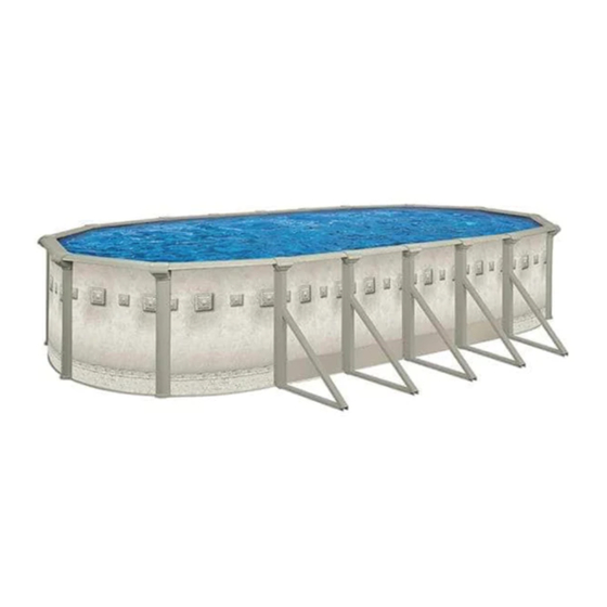
ASSEMBLY INSTRUCTIONS
We wish you a most pleasant and refreshing summer.
RADIUS (R)
WIDTH (D)
1.40m (4'7 1/2")
2.75m (9')
1.40m (4'7 1/2")
2.75m (9')
1.40m (4'7 1/2")
2.75m (9')
3.35m (11')
1.70m (5'7")
1.70m (5'7")
3.35m (11')
3.35m (11')
1.70m (5'7")
3.96m (13')
1.98m (6'6 3/4")
3.96m (13')
1.98m (6'6 3/4")
3.96m (13')
1.98m (6'6 3/4")
4.27m (14')
2.13m (7')
4.27m (14')
2.13m (7')
2.31m (7'7 1/2")
4.57m (15')
2.31m (7'7 1/2")
4.57m (15')
4.88m (16')
2.44m (8')
2.44m (8')
4.88m (16')
2.44m (8')
4.88m (16')
2.59m (8'6 1/2")
5.18m (17')
2.59m (8'6 1/2")
5.18m (17')
5.79m (19')
2.90m (9'-6")
5.79m (19')
2.90m (9'-6")
2.90m (9'-6")
5.79m (19')
INSSAO_ V1_2021-05-09
OVAL POOLS NBS
TOTAL LENGTH (E)
TRENCH (F)
4.45m (14'-7")
1.90m (6'-3 1/2")
5.03m (16'-6")
3.33m (10'-11")
6.12m (20'-1")
3.58m (11'-9")
5.03m (16'-5 3/4")
1.90m (6'-3 1/2")
5.85m (19-2 1/2")
3.33m (10'-11")
6.69m (21-11")
3.33m (10'-11")
5.94m (19'-6")
1.90m (6'-3 1/2")
7.59m (24'-11 1/2")
3.58m (11'-9")
8.43m (27'-8 1/4")
5.23m (17'-2 1/2")
5.48m (17'-11 3/4")
1.66m (5'-5 1/2")
7.14m (23'-5")
3.33m (10'-11")
6.27m (20'-7")
1.90m (6'-3 1/2")
7.95m (26'-1")
3.58m (11'-9")
6.30m (20'-8")
1.66m (5'-5 1/2")
7.96m (26'-1 1/2")
3.33m (10'-11")
9.64m (31'-7 1/4")
4.99m (16'-4 1/2")
8.38m (27'-6")
3.58m (11'-9")
10.05m (33')
5.23m (17'-2 1/2")
10.31m (33'-10")
5.24m (16'-4 1/2")
11.98m (39'-4")
6.90m (22'-8")
13.66m (44'-10")
8.56m (28'-1 1/2")
NBS
MODEL S
Advertisement

Subscribe to Our Youtube Channel
Related Manuals for Cornelius S


Summary of Contents for Cornelius S
- Page 1 INSSAO_ V1_2021-05-09 ASSEMBLY INSTRUCTIONS OVAL POOLS NBS MODEL S Dear Customer Congratulations! You have purchased a pool of superior quality and durability. To achieve the best possible results, follow the instructions carefully. Failure to follow the installation procedures may result in damage to your pool or property and void your warranty.
- Page 2 8cm (3 1/4”) deep. Top of framework must be For an oval pool, the bottom must absolutely be levelled, using a level with pool area. carpenter's level and a straight plank. Eliminate any protrusions. Ensure that the surface is free of debris such as rocks, wood, etc. 25cm 25cm 3-1/4"...
- Page 3 BOTTOM DRAIN ASSEMBLY (if applicable) Dig a hole 30 cm (12") wide by approximately 25 cm (10") deep in the center of the circumference. From the center hole to the projected location of the pool motor, dig a 15 cm (6") wide trench. Place the removed soil aside to be used later to cover the hose.
- Page 4 STRAIGHT SECTION BUTTRESS ASSEMBLY (continued) 2) Refer to Illustration 4.2. Assemble the buttress post using 3) Refer to Illustration 4.3. Cover the bolt heads with bolt cap bolts 1/2" X 3" X #13 (12,7 mm X 76,2 mm) (U), nuts (UU) and covers (W) and insert the styrofoam block (X) at both ends of foot washers (V).
- Page 5 TENSION STRAPS ASSEMLBY 1) Study illustrations and chart carefully. You are now ready to as- Illustration 6.1 TENSION semble the metallic tension straps. Refer to indications on the chart STRAPS for the exact number of tension straps per row according to their respective pool size.
- Page 6 WALL INSTALLATION Add sand. Choose the filter location beside a round section (never in a straight section). The starting point should be at that location where the skimmer and return holes are, and as close as possible to the fil- SKIMMER HOLE tration system.
- Page 7 SAND BASE FINISHING You can now spread approximately 10 cm (4") of compacting sand all around the inside base of the wall in order to protect the liner WALL from the cutting edges of the bottom tracks and the stone dust (if 30 cm (12") applicable), or install a prefabricated cove if available.
- Page 8 VINYL LINER INSTALLATION (continued) Installation detail of a bead liner with top track. Fill the pool with water up to the base of the wall before stopping Hang the liner on the top of the wall and install the top track to se- and removing the vacuum cleaner.
- Page 9 UPRIGHT POST TOP PLATE Straight section : Install the top plates into the buttress post in the Place the top seats on the top of the buttress post. Center the top straight section, and secure with two (2) screws ‘’Z’’. seat between the two the uprights and be certain to evenly distribute the ledges all around.
- Page 10 SEAT CAP INSTALLATION Straight section : Starting inside the pool, slide the seat cap on the Round section : Snap the seat cap starting outside the top seat. post until it hooks on the edge of the ledge. Then snap the other side inside the top seat. SEAT CAP SEAT CAP FIXE THE FRONT...
- Page 11 FILTRATION SYSTEM ASSEMBLY Assemble skimmer, inlet, drain, filter, pumps, hoses according to separate manufacturer’s instructions. Note: See 'Safety Information" Manual. PARTS LIST * SEE DRAWING PARTS NEXT PAGE ITEM DESCRIPTION POOL WALL (finished lenght, inch) BOLT & NUT FOR 52" (OR 54") WALL...
- Page 12 PARTS LIST STRAIGHT SECTION ROUND SECTION...
- Page 13 SAFETY AND FUN GO TOGETHER! SAFETY INFORMATION Read this before installing your above-ground pool. 12 775, Brault Street, Mirabel, Quebec, Canada J7J 0C4 Phone: 1 800 448-7384 Fax: 1 866 777-0167...
- Page 14 For your protection and for the safety of others, we We recommend that you purchase one of the following: A light, strong and rigid pole, frequently referred to as a Shepard’s recommend that lifesaving equipment be on hand near Crook, at least twelve feet long or a throwing rope at least ¼ inch in the pool at all times.
- Page 15 USAGE SAFETY INFORMATION...
- Page 16 5,44 x 13,36 m (17' 10" x 43' 10") 18'x44' 7,92m (26'-0") 2,90m (9'-6") Choisissez l'emplacement idéal pour votre piscine en tenant compte des lois municipales sur la distance des clôtures, celles des services publics sur la distance des fils électriques, ainsi que l'aménagement paysager prévu après l'installation.
- Page 17 équerres 8cm (3 1/4”). 122cm 6" (Se référer aux illustrations pour le dessin des couloirs). 15cm Tranchées pour dalles de ciment 2) S’assurez que ces couloirs soient plats et de niveau sans les Surface du sol compacter. 25cm 25cm 3-1/4" - 8cm 3-1/4"...
- Page 18 Fixez une des extrémités du long tuyau noir ou blanc dans l'embout du drain, en prenant soin au préalable d'appliquer de la colle sur l'embout du drain et à...
- Page 19 ÉCROU 1/2” RAINURES SECTION DROITE ET PLAQUES DE PRESSION 1) Positionnez les poteaux de renfort assemblés de l’étape 4 sur 3) Se reférer à l’illustration 5.2 : fixez les plaques de pression entre les omégas de base (foot beam) à l’aide de quatre (4) vis les dalles dans les tranchées préalablement creusées.
- Page 20 ASSEMBLÉS soin de placer la tête du boulon sur le dessus. 3) Fixez les bandes de tension ainsi assemblées aux omégas de base (foot beam) des deux côtés, à l'aide de quatre (4) vis stan- ÉCROU 1/4”x 5/8’’ dards ‘‘Z’’.
- Page 21 Si vous pouvez toujours voir l’icone, vous alignés. Si cela ne suffit pas, il vous faudra rouler le mur d'acier, devez inverser le chevauchement. revérifier les mesures en vous référant au tableau 1.1, ajuster les Sécurisez-le avec la boulonnerie dans chaque trou et bien sécuriser...
- Page 22 à former un remblai destiné à protéger MUR D'ACIER 30 cm (12") la toile des extrémités coupantes des rainures du bas et de la pous- sière de roche (si applicable). Ou bien, installez une doucine pré- fabriquée, si disponible.
- Page 23 Pour la section ronde: Enclenchez les poteaux de la section ronde sur les plaques du bas. Assurez-vous qu’ils sont bien accrochés. Pour les modèles avec vis; maintenez les poteaux en place dans les plaques du bas à l’aide de deux (2) vis ‘’Z’’.
- Page 24 INSTALLATION DES PLAQUES DU HAUT Section droite : Déposez les plaques du haut sur les poteaux de Placez les sièges sur les parties supérieures des poteaux de renfort. renfort dans la section droite, et maintenez-les en place à l’aide de Installez les sièges en vous assurant d’avoir un espace égal entre deux (2) vis ‘’Z’’.
- Page 25 INSTALLATION DU COUVRE-JOINT Section ronde : Glissez le couvre-joint de l’intérieur vers l’extérieur Section droite : Accrochez le couvre-joint sur le rebord extérieur de la piscine sous la partie supérieure du nez du poteau. des sièges. Ensuite, enclenchez vers l’intérieur de la piscine. COUVRE-JOINT COUVRE-JOINT ACCROCHEZ...
- Page 26 EMBOUT DE MOUSSE POUR OMÉGA BANDE DE TENSION BOULON ET ÉCROU 1/4" #20 X 5/8" (6,35 mm X 15,88 mm) VIS STANDARD (VIS #14 , 1" LONG.) NOTE: Vérifiez les quantités avec la liste de vérification incluse dans les boîtes.
- Page 27 LISTE DES PIÈCES (suite) SECTION DROITE SECTION RONDE...
- Page 28 LE PLAISIR PASSE D’ABORD ET AVANT TOUT PAR LA SÉCURITÉ CONSIGNES DE SÉCURITÉ Veuillez lire ceci avant de procéder à l’installation de votre piscine hors terre. 12 775, rue Brault, Mirabel, Québec, Canada J7J 0C4 Téléphone : 1 800 448-7384...
- Page 29 à d’autres exigences particulières. marches de piscine : votre échelle ou vos marches doivent rencon- trer les normes de sécurité ainsi que celles de votre région. Une util- AVERTISSEMENT: Toutes les composantes tels que le système de isation sécuritaire de l’échelle de la piscine est déterminante dans la...
- Page 30 CONSIGNES DE SÉCURITÉ LORS DE L’UTILISATION DE LA PISCINE...
Need help?
Do you have a question about the S and is the answer not in the manual?
Questions and answers