Advertisement
Quick Links
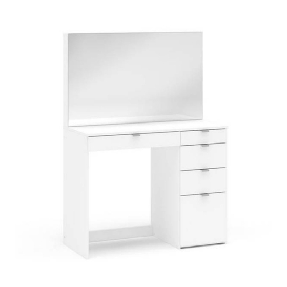
Ava 5 Drawer Dressing Table
Important before assembly:
Read these instructions carefully before assembling or using the product.
Please check the contents of the boxes before attempting to assemble this product. The instructions will
have a checklist of parts and fittings.
It would be sensible to lay a rug or a carpet on the floor where you intend to assemble the product, to avoid
scratches and damaging the product or the floor.
Assemble the product as close to its intended final location/room as possible.
Do NOT use any power tools as this may damage the frame.
Health & Safety:
This product or some parts of this product will be heavy. Please use an assistant when lifting.
Please keep small parts out of reach of children.
Always use on a level, even surface.
DO NOT jump on the product or any of its parts.
DO NOT use this product if any parts are missing, damaged or worn.
DO NOT use this product unless all fixings are secured.
Please keep these instructions for future reference.
Assembly Instructions
Title of Product
.
.
www.happybeds.co.uk
Advertisement

Related Manuals for Happybeds Ava 5 Drawer Dressing Table


Summary of Contents for Happybeds Ava 5 Drawer Dressing Table
- Page 1 Assembly Instructions Title of Product Ava 5 Drawer Dressing Table Important before assembly: Read these instructions carefully before assembling or using the product. Please check the contents of the boxes before attempting to assemble this product. The instructions will have a checklist of parts and fittings.
- Page 2 Never drag or push the pieces across a hard or stone floor as this will cause damage to the joints. Use a carpet or a rug for extra care. If you have problems assembling or have damaged or missing pieces, please contact us by visiting: https://www.happybeds.co.uk/customer-service...
- Page 3 Vendor: S000139 Parts List Description Description Part Part Upper base Bottom right of drawer side Upper left right side Bottom left of drawer side Rear right upper of drawer Left side Rear intermediate of drawer Division Bottom of drawer rear Right side Bottom left of drawer Tray upper left...
- Page 4 Hardware List Description Part 5 x 60 mm Screw Glue Small plastic foot Trapeze Metalic bracket Metalic angle plates Bushing 8 x 30 mm Wooden Dowel 8 x 50 mm Wooden Dowel Structural Screw Allen Key Structural Screw Cover Simple Minifix Screw Cam Lock Bore patch adhesive Nail...
- Page 5 Vendor: S000139 Step 1: Insert hardware part E using small mallet (not provided). DO NOT use any power tools as this may damage the frame and will invalidate any claim. Step 2: Attach the hardware J using the a screwdriver (not provided). DO NOT use any power tools as this may damage the frame and will invalidate any claim.
- Page 6 Vendor: S000139 Step 4: Attach hardware part E using a small mallet (not provided) and to the hardware part A1 and A3. DO NOT use any power tools as this may damage the frame and will invalidate any claim. (2x) (2x) Step 5: Attach hardware part E using a small mallet (not provided) and to the hardware part A1.
- Page 7 Vendor: S000139 Step 7: Insert hardware part E using small mallet (not provided). DO NOT use any power tools as this may damage the frame and will invalidate any claim. Step 8: Attach hardware part (B5) using hardware part S and screwdriver (not provided). DO NOT use any power tools as this may damage the frame and will invalidate any claim.
- Page 8 Vendor: S000139 Step 10: Attach the hardware part E to the division (06) using a small mallet (not provided) and attach the hardware part VB using the hardware part R and a screwdriver (not provided) and then rotate the part and attach the hardware part VA using the hardware part P5 and a screwdriver (not provided).
- Page 9 Vendor: S000139 Step 12: Attach the upper base (01) and upper left right side (02) using the hardware G, H and I. DO NOT use any power tools as this may damage the frame and will invalidate any claim. Step 13: Attach the top (04) and upper left right side (02) using the hardware G and H.
- Page 10 Vendor: S000139 Step 14: Attach the division (06) to the tray upper left (08) and tray bottom left (09) using hardware part G and H. DO NOT use any power tools as this may damage the frame and will invalidate any claim. Step 15: Attach the left side (05) to the tray upper left (08) and tray bottom left (09) using hardware part G,H and I.
- Page 11 Vendor: S000139 Step 16: Attach the tray bottom right rear (10) and tray lower right front (11) to the division (06) using hardware part G, H and I. DO NOT use any power tools as this may damage the frame and will invalidate any claim. Step 17: Attach the right side (07) to the tray bottom right rear (10) and tray lower right front (11) using hardware part G, H and I.
- Page 12 Vendor: S000139 Step 18: Join the top (04) to the left side (05), division (06) and right side (07) using hardware part L and a screwdriver (not provided). DO NOT use any power tools as this may damage the frame and will invalidate any claim. Step 19: Attach hardware part A2 to the o the left side (05), division (06) and right side (07) using hardware part N and small mallet (not provided).
- Page 13 Vendor: S000139 Step 20: Attach the back (25) using the hardware part N and a small mallet (not provided) using the hardware part B5 and S, attach mirror panel (27) in upper left right side (2). DO NOT use any power tools as this may damage the frame and will invalidate any claim. Step 21: Insert to the hardware part VB at division (06), using the hardware part R and a screwdriver (not provided)
- Page 14 Vendor: S000139 Step 22: To secure the item to the wall use hardware A, B3 and B7 and a screwdriver (not provided), then attach the hardware part S to the item with a screwdriver (not provided). DO NOT use any power tools as this may damage the frame and will invalidate any claim. Step 23: Attach the left side of drawer (72) and the right side of drawer (73) to the Rear left upper of drawer (18) and the bottom left of drawer (22) using the hardware O and a screwdriver (not provided).
- Page 15 Vendor: S000139 Step 24: Attach the top left of drawer front (12) using hardware part A1, and P with a screwdriver (not provided). DO NOT use any power tools as this may damage the frame and will invalidate any claim. Step 25: Attach the handle X4 to the top left of drawer front (12) using hardware part P5 and a screwdriver (not provided).
- Page 16 Vendor: S000139 Step 26: Attach the hardware part VC and VD to the left side of drawer (78) and right side of drawer (79) using the hardware part P5 and a screwdriver (not provided). DO NOT use any power tools as this may damage the frame and will invalidate any claim. THE UNDERSIDE OF THE DRAWER Step 27: Attach the left side of drawer (72) and the right side of drawer (73) to the rear right upper of drawer (19)
- Page 17 Vendor: S000139 Step 28: Attach the top right of drawer front (13) using hardware part A1, and P with a screwdriver (not provided). DO NOT use any power tools as this may damage the frame and will invalidate any claim. Step 29: Attach the handle X4 to the top right of drawer front (13) using hardware part P5 and a screwdriver (not provided).
- Page 18 Vendor: S000139 Step 30: Attach the hardware part VC and VD to the left side of drawer (72) and right side of drawer (73) using the hardware part P5 and a screwdriver (not provided). DO NOT use any power tools as this may damage the frame and will invalidate any claim. THE UNDERSIDE OF THE DRAWER Step 31: Attach the left side of drawer (78) and right side of drawer (79) to the rear intermediate of drawer (20)
- Page 19 Vendor: S000139 Step 32: Attach the intermediate of drawer front (14) to the left side of drawer (78) and right side of drawer (79) using hardware part A1, L and a screwdriver (not provided). Then insert the hardware part M to the left side of drawer (78) and right side of drawer (79).
- Page 20 Vendor: S000139 Step 34: Attach the hardware part VC and VD to the left side of drawer (78) and right side of drawer (79) using the hardware part P5 and a screwdriver (not provided). DO NOT use any power tools as this may damage the frame and will invalidate any claim. THE UNDERSIDE OF THE DRAWER Step 35: Attach the bottom left of drawer side(16) and the bottom right of drawer side(17) to the bottom of drawer...
- Page 21 Vendor: S000139 Step 36: Attach the bottom of drawer front (15) to the bottom right of drawer side (17) and bottom left of drawer side (18) using hardware part A1, L and a screwdriver (not provided). Then insert the hardware part M to the bottom right of drawer side (17) and bottom left of drawer side(18).
-
Page 22: Additional Information
Vendor: S000139 Step 38: Attach the hardware part VC and VD to the bottom right of drawer side (17) and bottom left of drawer side (18) using the hardware part P5 and a screwdriver (not provided). DO NOT use any power tools as this may damage the frame and will invalidate any claim. THE UNDERSIDE OF THE DRAWER Step 39: Join the drawers to the assembled section. -
Page 23: General Care And Maintenance
If this is not adhered to, it could result in failure to the product that will invalidate the warranty. For more information on cleaning and product care visit: https://www.happybeds.co.uk/help-and-advice Notes We’ve tried to make this product as easy to assemble as possible. In the unlikely event that...
Need help?
Do you have a question about the Ava 5 Drawer Dressing Table and is the answer not in the manual?
Questions and answers