Table of Contents
Advertisement
Quick Links
PRECAUTIONS
Please follow these precautions:
To prevent fire or shock hazard, do not expose the unit to rain or moisture.
To prevent electrical shock, do not open the cabinet. Refer to qualified
personnel for service only.
Do not use the unit continuously for more than 24 hours with camera auto
focus on. It may cause damage to the camera lens.
Be careful not to spill water or other liquids onto the unit, or allow combustible
or metallic objects to get inside the cabinet.
Unplug the visualizer from the wall outlet when it is not in use for
an extended period of time.
Clean cabinet with a soft cloth lightly moistened with a mild detergent.
Clean lens carefully with an air spray or soft dry cloth to avoid scratching.
When lamps flash or become dark, they should be replaced with new ones.
Avoid interchanging arm lights and back light frequently.
Remove the camera lens cap before power the unit on.
1
Advertisement
Table of Contents

Related Manuals for Qomo QView QD3300


Summary of Contents for Qomo QView QD3300
- Page 1 PRECAUTIONS Please follow these precautions: To prevent fire or shock hazard, do not expose the unit to rain or moisture. To prevent electrical shock, do not open the cabinet. Refer to qualified personnel for service only. Do not use the unit continuously for more than 24 hours with camera auto focus on.
-
Page 2: Table Of Contents
CONTENTS: PARTS IDENTIFICATION ................. 3 CONTROL PANEL .................... 3 BUTTON INSTRUCTION .................. 4 REMOTE CONTROL ..................5 CONNECTIONS ....................6 BASIC PREPARATIONS ................... 7 WORKING ON THE STAGE ................10 WORKING OUTSIDE THE STAGE ..............10 LIGHT ......................10 ADJUSTING IMAGE SIZE ................11 WORKING WITH NEGATIVES ............... -
Page 3: Parts Identification
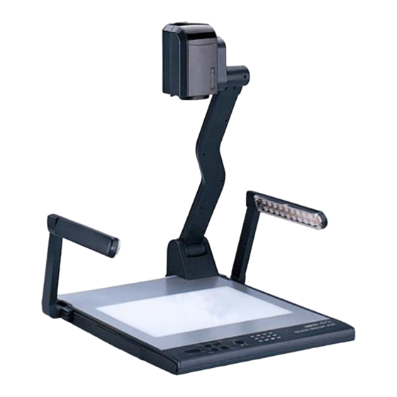
SPECIFICATIONS ................... 21 PARTS IDENTIFICATION Camera Camera stand Arm lights Button instruction Connectors Back light Connectors Remote control slot Stage Operation panel CONTROL PANEL Rot (Rotate the image) Frz (Freeze the image) Neg (Display film negatives) Text (Switch between image/text mode) Save (Save captured images) (Freeze the top 1/8 of the screen) Title... -
Page 4: Button Instruction
x 4 matrix) Ppw (Control the projector On/Standby) Pin (Projector input signal selection) (No function) POWER (Control the visualizer On/Off) CCD (CCD input signal selection) PC1/PC2 (RGB input signal selection) LAMP (Control the arm lights and back light) AUTO (To auto adjust brightness, auto white balance and auto focus) (Zoom in and out) BUTTON INSTRUCTION... -
Page 5: Remote Control
REMOTE CONTROL POWER (Control the visualizer On/Off) SAVE (Save captured images) RECALL (Multiple Screen Display) LAMP (Control the arm lights and back light) ROTATE (Rotate the image) FREEZE (Freeze the image) NEG (Display film negatives) MIRROR (V-Reverse the image) XGA (No function) TEXT (Switch between image/text mode) B&W (Switch between Color mode and Black &... -
Page 6: Connections
TELE/ IDE (Increase and decrease magnification) FAR/NEAR (Focus near or far) AUTO (To auto adjust brightness, auto white balance and auto focus) CCD/PC1/PC2 (CCD/RGB input signal selection) S-VIDEO/VIDEO (No function) VOLUME+/- (Increase or decrease the volume) RED+/- (Increase or decrease the red hue) BLUE+/- (Increase or decrease the blue hue) BRIGHT+/- (Increase or decrease the brightness) SCROLL /... -
Page 7: Basic Preparations
BASIC PREPARATIONS 1. Place one hand firmly on the base of the visualizer, while carefully lifting up the camera stand using the other hand. 2. Open the arm lights and rotate the camera head until they are properly positioned. Arm lights 3. - Page 8 Step 2: Connect to the projector. Connect the PROJECTOR port to the projector’s RGB IN port using the RGB cable. You can also control a projector using the controls on the visualizer by connecting the projector to the visualizer using a 6-pin to 9-pin RS232 cable.
- Page 9 Note: You can connect a laptop computer to the RGB IN port of side panel using a RGB cable. Step 4: Connect to the video equipment. Step 5: Connections for external control from the computer. Use the computer RS232 cable (9-pin to 9-pin) to make the connections displayed below to control the visualizer from an external computer.
-
Page 10: Working On The Stage
4. Turn on the power by pressing the “POWER” button. WORKING ON THE STAGE 1. Place your material on the platform. 2. Select the enlargement required using the “ T ” and “ ” buttons. 3. Adjust the focus using the “Near” and “Far” buttons or “AUTO” button. WORKING OUTSIDE THE STAGE To show a 3-dimensional object using the visualizer, place the object on the working surface and adjust the “... -
Page 11: Adjusting Image Size
ADJUSTING IMAGE SIZE To reduce or enlarge the image size displayed on the screen, press the “ T ” (Zoom in) or “ ” (Zoom out) button. WORKING WITH NEGATIVES The visualizer is automatically set to display normal materials on the screen when the power is on. -
Page 12: Brightness Adjustment
adjustment, etc.). BRIGHTNESS ADJUSTMENT If the image effect is not satisfactory, you can adjust the brightness to get a better image effect. Use the “BRIGHT +” or “BRIGHT -” button to adjust the brightness. To increase the brightness, press the “BRIGHT +” button. To decrease it, press the “BRIGHT -”... -
Page 13: Projector On/Standby
PROJECTOR ON/STANDBY Press the “POWER” button to turn on the visualizer’s power and press the “Ppw” button to turn the projector power on. To place the projector on standby after use, press the “Ppw” button and hold for more than 2 seconds. -
Page 14: Installing Visualizer Software
“DIV.”, the stored first sixteen images can be displayed in a 4 x 4 matrix. button to Select the image that you want to display, then click button to display the selected image, press button to delete the selected image. Press to exit the 4 x 4 image display mode. -
Page 15: Usb Port
effect. Use the USB2.0 cable provided to connect your computer to the visualizer before your computer is restarted. USB PORT The USB port can be used to store still images from the visualizer in a computer. Connect the visualizer to your computer with the supplied USB cable. -
Page 16: Controlling Visualizer By Computer
Click “Capture”—> “Start Capture”, input the file name in dialog box, or click icon on the toolbar, then input the file name in dialog box. If you want to set the time limit for the capture, select “Capture” ->“Set Time Limit“... - Page 17 can control various projector with the visualizer. 1. Connect the visualizer to the projector with the RGB ˆVIDEO ˆS-VIDEO cables. 2. Connect the RS232 cable to the computer’s connector. The visualizer’s RS232 port is located on its right side. 3. After completion of the connection, turn on the visualizer ¨click [start] -> [All Programs] ->...
- Page 18 The input format of projector’s control code is as follows: a. If the data is in the numerical value format, please input data directly, block them off with comma, do not distinguish lowercase and uppercase. For example: the “POWER ON” code in Hitachi projector manual is : BE EF 03 06 00 BA D2...
- Page 19 Then use buttons on the operation panel to control the projector. The visualizer provides a 6-pin to 9-pin RS232 cable. If this cable does not match to your projector’s RS232 port, an additional RS232 cable is needed. This additional RS232 cable can be made based on the pin location of the projector’s RS232 control port.
-
Page 20: Folding The Unit
Click the projector control buttons on the visualizer’s operating panel to check if the control code that the program received is the same as the sending code. If the receiving code is same to the sending code, the input codes are correct. If the visualizer can not control the projector, please do the following. - Page 21 2. Carefully fold the camera stand down to the front panel. Cautions: a. Do not lay the unit down flat. b. Do not try to stand it on its rear or sides. c. Do not try to pick up this unit by pulling the camera stand. NOT THIS WAY SPECIFICATIONS Resolution...
- Page 22 White balance Auto Negative/positive conversion Black/white and color selection Yes Image Split Image Title Image Freeze Image Save & Recall 16 frames save, 4 x 4 multiple screen display Arm light: 1.5W LED lamps x 2 Back light: 4W LED lamps Lights MIC IN (phone jack)(1) PC Audio (2)
- Page 23 USB cable Audio convert cable AC adapter User’s manual Software CD Infrared remote control Warranty card * Design and specifications are subject to change without prior notice.
Need help?
Do you have a question about the QView QD3300 and is the answer not in the manual?
Questions and answers