Table of Contents
Advertisement
Quick Links
PRECAUTIONS
Please follow these precautions:
To prevent fire or shock hazard, do not expose the unit to rain or moisture.
To prevent electrical shock, do not open the cabinet. Refer to qualified
personnel for service only.
Do not use the unit continuously for more than 24 hours with camera auto
focus on. It may cause damage to the camera lens.
Be careful not to spill water or other liquids onto the unit, or allow combustible
or metallic objects to get inside the cabinet.
Unplug the visualizer from the wall outlet when it is not in use for
an extended period of time.
Clean cabinet with a soft cloth lightly moistened with a mild detergent.
Clean lens carefully with an air spray or soft dry cloth to avoid scratching.
When lamps flash or become dark, they should be replaced with new ones.
Avoid interchanging arm lights and back light frequently.
Remove the camera lens cap before power the unit on.
1
Advertisement
Table of Contents

Subscribe to Our Youtube Channel
Related Manuals for Qomo QD3700


Summary of Contents for Qomo QD3700
- Page 1 PRECAUTIONS Please follow these precautions: To prevent fire or shock hazard, do not expose the unit to rain or moisture. To prevent electrical shock, do not open the cabinet. Refer to qualified personnel for service only. Do not use the unit continuously for more than 24 hours with camera auto focus on.
-
Page 2: Table Of Contents
CONTENTS: PARTS IDENTIFICATION ................3 CONTROL PANEL ..................3 BUTTON INSTRUCTION................4 REMOTE CONTROL ..................5 CONNECTIONS ..................... 6 BASIC PREPARATIONS................. 6 PAL/NTSC VIDEO OUTPUTS ...............11 WORKING ON THE STAGE ................11 WORKING OUTSIDE THE STAGE..............11 LIGHT ......................11 ADJUSTING IMAGE SIZE ................12 WORKING WITH NEGATIVES .............. -
Page 3: Parts Identification
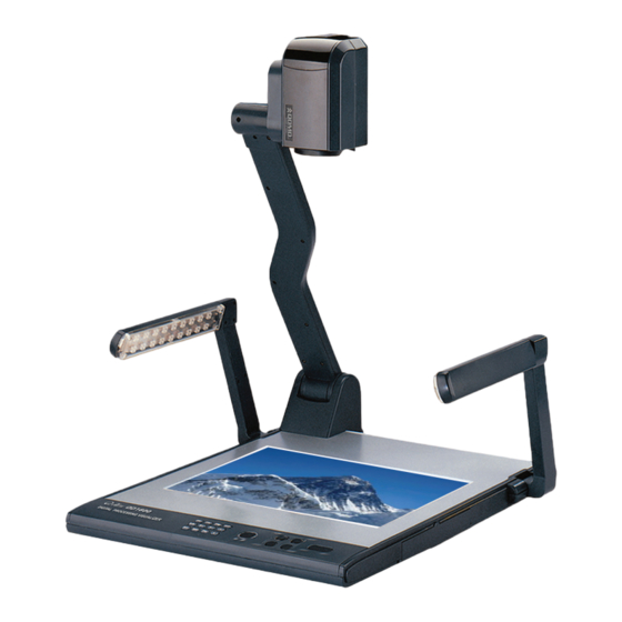
CONTROLLING PROJECTOR BY VISUALIZER.......... 18 FOLDING THE UNIT..................21 SPECIFICATIONS ..................23 PARTS IDENTIFICATION Camera Camera stand Arm lights Button instruction Connectors Back light Connectors Remote control slot Stage Operation panel CONTROL PANEL Rot (Rotate the image) Frz (Freeze the image) Neg (Display film negatives) Text (Switch between image/text mode) Save (Save captured images) -
Page 4: Button Instruction
Mem (Multiple Screen Display, the stored images will be displayed in a 4 x 4 matrix) Ppw (Control the projector On/Standby) Pin (Projector input signal selection) (Move the image up/down) POWER (Control the visualizer On/Off) CCD/PC1/PC2 (CCD/RGB input signal selection) S-VIDEO/VIDEO (S-Video/ Video input signal selection) LAMP (Control the arm lights and back light) AUTO (To auto adjust brightness, auto white balance and auto focus) -
Page 5: Remote Control
REMOTE CONTROL POWER (Control the visualizer On/Off) SAVE (Save captured images) RECALL (Multiple Screen Display) LAMP (Control the arm lights and back light) ROTATE (Rotate the image) FREEZE (Freeze the image) NEG (Display film negatives) MIRROR (V-Reverse the image) XGA (Switch between XGA (1024 x 768) and SXGA (1280 x 1024) mode) TEXT (Switch between image/text mode) B&W (Switch between Color mode and Black &... -
Page 6: Connections
TELE/ IDE (Increase and decrease magnification) FAR/NEAR (Focus near or far) AUTO (To auto adjust brightness, auto white balance and auto focus) CCD/PC1/PC2 (CCD/RGB input signal selection) S-VIDEO/VIDEO (S-Video/ Video input signal selection) VOLUME+/- (Increase or decrease the volume) RED+/- (Increase or decrease the red hue) BLUE+/- (Increase or decrease the blue hue) BRIGHT+/- (Increase or decrease the brightness) SCROLL /... - Page 7 1. Place one hand firmly on the base of the visualizer, while carefully lifting up the camera stand using the other hand. 2. Open the arm lights and rotate the camera head until they are properly positioned. Arm lights 3. Making connections: Before making any connections, turn off all the power.
- Page 8 Rear Panel S-VIDEO AUDIO VIDEO S-VIDEO AUDIO VIDEO PROJECTOR OUT -COMPUTER- IN OUT-12V- IN AUDIO AUDIO IN RGB Input RS232 Cable Screen Projector Side Panel PROJECTOR RGB IN AUDIO IN RS232 Connect the PROJECTOR port to the projector’s RGB IN port using the RGB cable.
- Page 9 Rear Panel To the Monitor S-VIDEO AUDIO VIDEO S-VIDEO AUDIO VIDEO AUDIO AUDIO IN PROJECTOR OUT -COMPUTER- IN OUT-12V- IN USB Connector RGB Output RS232 Cable Computer PROJECTOR RGB IN AUDIO IN RS232 Side Panel Note: You can connect a laptop computer to the RGB IN port of side panel using a RGB cable.
-
Page 10: Side Panel
Step 5: Connect to the second video equipment with video input. Video Cable Video out Audio out Video equipment Rear Panel AUDIO VIDEO S-VIDEO AUDIO VIDEO AUDIO S-VIDEO -COMPUTER- OUT-12V- IN AUDIO IN PROJECTOR Projector Color monitor Video in Step 6: Connections for external control from the computer. Side Panel PROJECTOR MIC RGB IN... -
Page 11: Pal/Ntsc Video Outputs
PAL/NTSC VIDEO OUTPUTS The S-Video and composite video outputs are set to PAL (NTSC) during manufacturing. WORKING ON THE STAGE 1. Place your material on the platform. 2. Select the enlargement required using the “ T ” and “ ” buttons. 3. -
Page 12: Adjusting Image Size
The arm lights turn on The back light turns on All the lights turn off ADJUSTING IMAGE SIZE To reduce or enlarge the image size displayed on the screen, press the “ T ” (Zoom in) or “ ” (Zoom out) button. WORKING WITH NEGATIVES The visualizer is automatically set to display normal materials on the screen when the power is on. -
Page 13: Freezing Image
Press the “AUTO” button to auto focus. Press the “FAR” or “NEAR” button to focus manually. FREEZING IMAGE To show a still image on the screen, when the output signal is RGB, press the “Frz” button. The frozen image cannot be adjusted (Zoom in/out, color adjustment, etc.). -
Page 14: Video Inputs
VIDEO INPUTS Press the “S-VIDEO/VIDEO” button to switch between S-Video and composite video signals. RGB INPUTS Use the “CCD/PC1/PC2” button to switch between CCD and different RGB signals. Each time the “CCD/PC1/PC2” button is pressed, it provides seamless transitions among different sources such as Camera (CCD), COMPUTER (IN), and RGB (IN). -
Page 15: Infrared Remote Control
INFRARED REMOTE CONTROL The visualizer’s remote control can control the camera from different angels. On the left side of the visualizer stage, there is a built-in remote control storage compartment where you can store the remote control when it is not in use. Please note that an infrared remote control can only be used up to a certain distance to the unit. -
Page 16: Usb Port
If it does not start automatically, after inserting the CD-ROM, Click [Start] -> [My Computer], and double click (the CD-ROM drive letter might be different in different computer systems), and then the above screen will appear immediately. Click the Install Capture Program button to install the program that captures images in the AVI or JPG format. -
Page 17: Usb Image Capture
USB IMAGE CAPTURE You can capture and control images on the visualizer from a computer connected with a USB connector. Click [Start] -> [Program] -> [VideoCap] -> “VideoCapx.xx” (x.xx is software’s to open the software. version) A. Static Images Snap Click “Capture”—>“Capture Frame”, input the file name in dialog box, or you can click icon on the toolbar, then input file name in dialog window. -
Page 18: Controlling Visualizer By Computer
CONTROLLING VISUALIZER BY COMPUTER You can control the visualizer from a computer connected with a RS232 connector. A. Connect the computer and the visualizer using the RS232 cable. B. Double click X:\ 232 Control\Control Panel (you can open this file from the CD and double click it, or copy this file to any directory on your computer’s hard drive and double click to launch it). - Page 19 When the indicator of “Current RS-232 Connection Status” is green, that means the connection between the visualizer and the computer’s RS232 connector is good. If the indicator is red, please check if the RS232 cable is connected correctly. When all the cables are connected correctly, please click “Projector”...
- Page 20 In the POWER ON box, input ’POWR 1’, 0d, 0a (Remarks: There are 3 spaces after POWER, 0d, 0a is enter.) Input other codes in the same way. c. If the data is in the numerical value and character format, then synthesize the above-mentioned formats.
- Page 21 Connect the visualizer to a computer with a RS232 cable (Please disconnect the projector from the RS232 port first) and select the Baud Rate and Parity based on the projector’s Baud Rate, then click the “TEST” button to pop up the Projector Code Test dialog box, input the Baud Rate and Parity based on the projector’s Baud rate, then click “Open”.
- Page 22 Rotate the camera head clockwise until the camera head is parallel to the camera stand. 2. Carefully fold the camera stand down to the front panel. Cautions: a. Do not lay the unit down flat. b. Do not try to stand it on its rear or sides. c.
-
Page 23: Specifications
NOT THIS WAY SPECIFICATIONS Resolution SXGA (1280 x 1024),XGA (1024 x 768) Total Pixels 2,000,000 12 x optical zoom, 10 x electrical zoom Lens Camera Rotation Vertically 330° Focus Auto/manual selectable White balance Auto Negative/positive conversion Black/white and color selection Image Split Image Title Image Freeze... - Page 24 RGB DB15FLC (2) C Video OUT (RCA) (1) Output connectors S Video OUT (4-pin DIN) (1) Audio OUT (Mini Jack) (1) Operating system Windows XP SP2 (Service pack 2) Hardware Requirement CPU higher than P2.4GHz Memory higher than 256 MB USB connector frames/sec RS-232 connector...
Need help?
Do you have a question about the QD3700 and is the answer not in the manual?
Questions and answers