Table of Contents
Advertisement
Quick Links
Advertisement
Table of Contents

Related Manuals for LINOVISION IOT-S500 Series


Summary of Contents for LINOVISION IOT-S500 Series
- Page 1 IOT-S500 Series User Guide Hangzhou Linovision Co., Ltd.
- Page 2 The device must not be remodeled in any way. The device is not intended to be used as a reference sensor, and Linovision will not should responsibility for any damage which may result from inaccurate readings.
- Page 3 For assistance,please contact Linovision technical support: E-mail:sales@linovision.com Tel:+86 571-8670 8175 Website:wwww.linovision.com Revision History Date Doc Version Description Nov. 23, 2020 V 1.0 Initial version...
-
Page 4: Table Of Contents
4.1 LoRaWAN Settings................... 10 4.2 Basic Settings....................11 4.3 Calibration......................11 4.4 Threshold and Alarm..................12 5. Cloud Management....................12 5.1 Add a Linovision Gateway.................12 5.2 Add IOT-S500 to Cloud..................13 6. Sensor Payload......................14 6.1 Basic Information..................... 14 6.2 Sensor Data......................14 6.3 Downlink Commands..................16... -
Page 5: Product Introduction
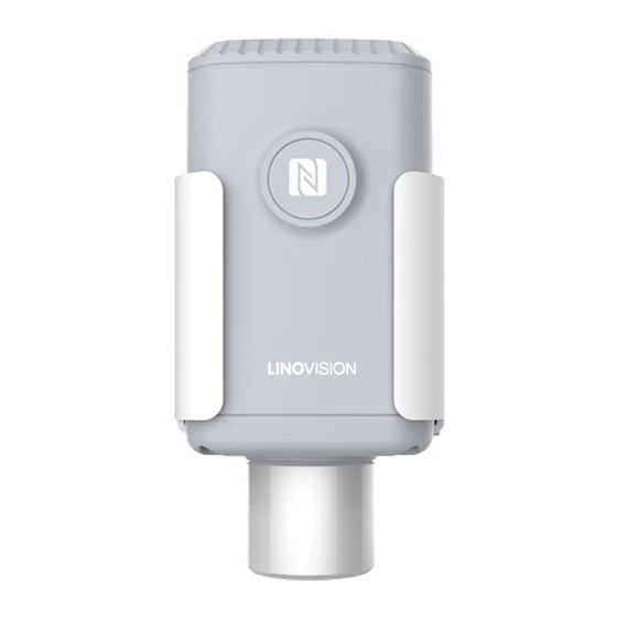
Low power consumption with 19000mAh replaceable battery 2. Hardware Introduction IOT-S500 series sensors is made up of a LoRa transceiver and a sensor. Among them, ultrasonic sensors and gas sensors are combined with LoRa transceiver. 2.1 Hardware Overview Front View of IOT-S500: ①LoRa Antenna (Internal) -
Page 6: Dimensions(Mm)
Front View of IOT-S500CO2 ①LoRa Antenna (Internal) ②NFC Area ③Vent Tube Front View of IOT-S500UDL-W050 ①LoRa Antenna (Internal) ②NFC Area ③Ultrasonic Horn Back View: ④Battery (Internal) ⑤Wall Mounting Holes ⑥Pole Mounting Holes 2.2 Dimensions(mm) IOT-S500... -
Page 7: Power Button Descriptions
IOT-S500CO2 IOT-S500UDL-W050 2.3 Power Button Descriptions Note: IOT-S500 can also be turned on/off and reset via Mobile APP or Toolbox. Function Action LED Indication Turn On Press and hold the button for more than 3s. Off → Static Green Turn Off Press and hold the button for more than 3s. -
Page 8: Basic Configuration
3. Basic Configuration In order to protect the security of sensor, password validation is required when configuring via unused phone . Default password is 123456. 3.1 Configuration via Smartphone APP Preparation: Smartphone (NFC supported) Toolbox APP: download and install from Google Play or Apple Store. ... - Page 9 3.1.2 Template Configuration Template settings only work for easy and quick device configuration in bulk. Note: Template function is allowed only for sensors with the same model and LoRa frequency band. 1. Go to “Template” page on the APP and save current settings as a template. 2.
-
Page 10: Advanced Feature Description
4. Slide the template item to the left to edit or delete the template. 4. Advanced Feature Description 4.1 LoRaWAN Settings Parameters Description Default Device EUI Unique ID of the sensor. It can be found on the label. On the label App EUI App EUI of the sensor. -
Page 11: Basic Settings
Session Key 52613230313823 Spread Factor Select spread factor from SF7 to SF12. SF10-DR2 If the sensor does not receive ACK package from Confirmed Mode Disabled network server, it will resend data 3 times most. Sensor will send specific mounts of LoRaMAC Rejoin Mode packages to check connection status regularly. -
Page 12: Threshold And Alarm
The sensor will detect and check whether the value is triggered again after Data Collecting Interval data collecting interval. 5. Cloud Management 5.1 Add a Linovision Gateway 1. Enable “Linovision” type network server and “Cloud” mode in gateway web GUI. Note: Ensure gateway has accessed the Internet. -
Page 13: Add Iot-S500 To Cloud
2. Go to “My Devices” page and click “+New Devices” to add gateway to Cloud via SN. Gateway will be added under “Gateways” menu. 3.Check if gateway is online in Cloud. 5.2 Add IOT-S500 to Cloud 1. Go to “My Devices” page and click “+New Devices”. Fill in the SN of IOT-S500 and select associated gateway. -
Page 14: Sensor Payload
dashboard for it. 6. Sensor Payload All data are based on following format(HEX): Channel1 Type1 Data1 Channel2 Type2 Data2 Channel 3 1 Byte 1 Byte N Bytes 1 Byte 1 Byte M Bytes 1 Byte 6.1 Basic Information IOT-S500 sensors report basic information of sensor everytime joining the network. Channel Type Data Example... - Page 15 10 01 => 01 10 = 272 67 (Temperature) 10 01 Temp=272*0.1=27.2°C 71=>113 68(Humidity) Hum=113*0.5=56.5% 7d(CO ) 67 04 67 04 => 04 67 =1127 ppm 73(Barometric 68 27=>27 68=10088 68 27 Pressure) Pressure=10088*0.1=1008.8hPa IOT-S500LGT Channel Type Data Example Description 64=>100 75(Battery Level) Battery level =100%...
-
Page 16: Downlink Commands
10 01 => 01 10 = 272 67 (Temperature) 10 01 Temp=272*0.1=27.2°C 71=>113 68(Moisture) Hum=113*0.5=56.5% 7d(Conductivity) f0 00 f0 00 => 00 f0 =240 µs/cm IOT-S500SWL Channel Type Data Example Description 64=>100 75(Battery Level) Battery level =100% 77 (Water Level) 02 00 02 00=>00 02=2cm IOT-S500UDL-W050... - Page 17 Appport 0x55 NetID 0x010203 The 5 to 12 digits of SN DevAddr e.g. SN = 61 26 A1 01 84 96 00 41 Then DevAddr = A1018496 AppKey 5572404C696E6B4C6F52613230313823 NwkSKey 5572404C696E6B4C6F52613230313823 AppSKey 5572404C696E6B4C6F52613230313823 -END-...
Need help?
Do you have a question about the IOT-S500 Series and is the answer not in the manual?
Questions and answers