Table of Contents
Advertisement
Quick Links
Advertisement
Table of Contents

Subscribe to Our Youtube Channel
Related Manuals for Intellisystem IT-600-IPC Series


Summary of Contents for Intellisystem IT-600-IPC Series
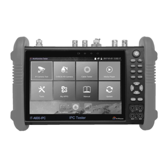
- Page 1 IT-600-IPC Series IP Camera Tester User Manual (V01.00)...
- Page 2 Thank you for purchasing the IP camera tester. Please read the manual before using the IP camera tester and use properly. For using the IP camera tester safely, please first read the「Safety Information」carefully in the manual. The manual should be kept well in case of reference. Keep the S/N label for after-sale service within warranty period.
-
Page 3: Table Of Contents
Content 1 .Safety information ------------------------------------------------------------------------------------------------- 1 2. IP Camera Tester Introduction ----------------------------------------------------------------------------------- 2 2.1 General ------------------------------------------------------------------------------------------------------ 2 2.4 Packing list -------------------------------------------------------------------------------------------------- 3 2.5 Function interface ------------------------------------------------------------------------------------------ 4 3. Operation ----------------------------------------------------------------------------------------------------------- 7 3.1 Installing the Battery --------------------------------------------------------------------------------------- 7 3.2 Instrument connection ------------------------------------------------------------------------------------- 8 3.2.1 IP camera connection ------------------------------------------------------------------------------------ 8 3.2.2 Analog camera connection ------------------------------------------------------------------------------ 9 3.2.3 HD Coaxial camera connection ---------------------------------------------------------------- 10... - Page 4 3.3.15 TVI camera test ( *Optional )--------------------------------------------------------------- 61 3.3.16 AHD camera test ( *Optional ) ------------------------------------------------------------- 63 3.3.17 Network tool ------------------------------------------------------------------------------------ 64 (1)IP address scan ---------------------------------------------------------------------------------- 64 (2)PING Test ---------------------------------------------------------------------------------------- 65 (3)Network test (Ethernet bandwidth test)------------------------------------------------------- 65 (4)Port Flashing ------------------------------------------------------------------------------------- 69 (5)DHCP server ------------------------------------------------------------------------------------- 70 (6)Trace route --------------------------------------------------------------------------------------- 70 (7)Link monitor ------------------------------------------------------------------------------------- 71...
- Page 5 3.3.37 Office ------------------------------------------------------------------------------------------- 106 3.3.38 LED Flashlight --------------------------------------------------------------------------------- 106 3.3.39 Browser ----------------------------------------------------------------------------------------- 107 3.3.40 Notepad ----------------------------------------------------------------------------------------- 107 3.3.41 System Setting --------------------------------------------------------------------------------- 108 3.3.42 File explorer ------------------------------------------------------------------------------------ 113 3.3.43 Theme ------------------------------------------------------------------------------------------- 114 3. 4 Audio test ------------------------------------------------------------------------------------------------ 117 3.5 HDMI output -------------------------------------------------------------------------------------------- 117 3.6 PoE power output --------------------------------------------------------------------------------------- 117 3.7 DC12V 2A power output ------------------------------------------------------------------------------- 118 4.
-
Page 6: Safety Information
1 Safety information ◆ The tester is intended to use in compliance with the local rules of the electrical usage and avoid to apply at the places which are inapplicable for the use of electrics such as hospital, gas station etc. ◆... -
Page 7: Ip Camera Tester Introduction
◆ Never connect the meter with any voltage source while the function switch is in the current, resistance, capacitance, diode, continuity, otherwise it will damage the meter. ◆ Never perform capacitance measurements unless the capacitor to be measured has been discharged fully. -
Page 8: Packing List
2.4 Packing list 1) Tester 2) Adaptor DC12V 2A 3) Network cable tester 4) Polymer lithium ion battery (7.4V DC 5400mAh) 5) BNC cable 6) RS485 cable 7) SC, ST Connector(Only for optical power meter) 8) Multi-meter test leads one pair of red and black (only for the Multi-meter models) 9) Output Power cable 10) Audio cable 11) TDR alligator clamp (only for TDR models) -
Page 9: Function Interface
2.5 Function interface... - Page 10 Press more than 2 seconds, turn on or off the device ,short press to turn on or off the menu display Menu key, press it to call short- menu. 4xzoom the image displays. Far focus: Focus the image faraway Near focus: Focus the image nearby TELE: zoom in the image WIDE: zoom out the image Open/set ,Confirm the setting of parameters, open or enlarge the aperture...
- Page 11 The power indicator: it lights green while the tester is powered on by the adapter Top interface Bottom interface Visible red laser source emits Interface (Optional) DC12V2A power output , for provisional DC power supply HDMI IN (Optional ) CVBS IN/AHD /TVI/CVI Coaxial interface / ( BNC interface ) (AHD /TVI/CVI (Optional) ) Video signal output(BNC interface)/ cable tracer interface Optical power meter interface (Optional)
-
Page 12: Operation
SDI input (BNC interface) ( Optional) TDR cable test interface (Optional) HDMI output interface Micro SD card moveable,(comes with 8GB, supports up to 32GB) UTP cable port: UTP cable tester port/ Cable tracer port PSE power sourcing equipment. Tests PoE voltage PoE power supply output or LAN test port (Use to test PoE or non-PoE IP camera) Audio output and earphone interface Audio input... -
Page 13: Instrument Connection
The charging time can be extended for about 1 hour and the charging time within 12 hours will not damage the battery. Notice: Press the key several seconds to restore the default settings when the instrument works abnormally. Multi-meter: the red and black multi-meter pen must insert the corresponding port. Warnings: Instrument communication port is not permitted access circuit voltage over 6V, otherwise damage the tester. -
Page 14: Analog Camera Connection
Note: 1) If the IP camera requires PoE power, then connect the IP camera to the IP tester’s LAN port . The tester will supply PoE Power for the IP camera. Click on the icon POE to turn the PoE Power off or 2) If use the tester’s menu to turn off the tester’s PoE power supply, the PoE switch and the power sourcing equipment are allowed to connect to the tester’s PSE port, and the PoE power will be supplied to the IP camera by the tester’s LAN port. -
Page 15: Hd Coaxial Camera Connection
(1) Connect the camera's video output to the IP tester’s VIDEO IN. The image will display on the tester after pushing the PTZ icon. (2) CCTV IP Tester “VIDEO OUT” interface connect to the Video input of monitor and optical video transmitter and receiver, the image display on the tester and monitor. -
Page 16: Hdmi In
3.2.4 HDMI IN DVR or other device’s HDMI in port connect to tester’s HDMI in port, the meter will display input image. 3.3 OSD menu Press the key 2 seconds to turn on Press the key again to turn off short press the key to enter sleep mode, press it again to test. - Page 17 In Lite mode, Press the icon several seconds, can move the icon to other apps In lite mode, click the finger icon in the lower right corner to release lock icon, move icons and change function icons sequence. Normal mode ...
- Page 18 In normal mode, press icon several seconds, go screen management status. Change icons sequence and move it to common tools bar. You can move the icon to any pages; self-define the number of icons in any page. Make interface sample and individuality.
- Page 19 Create New Folder: Drag the icon to the folder in top right corner, enter the folder name. Icon will be auto placed in the new named folder. Press the folder several seconds, to change the folder name, you can move the icon out of folder, the folder will be auto deleted until move out all icons.
-
Page 20: Drop-Down Menu
3.3.2 Drop-down Menu Press and slide at right top right corner twice to open shortcut menu. The shortcut menu includes POE power output, IP settings, Wi-Fi, HDMI IN, CVBS, Video OUT, LAN, Brightness, settings etc. HDMI: Click HDMI IN to enter. In HDMI IN mode, it can converter test from analog to digital with dual test window IP &... -
Page 21: Short Cut-Menu
3.3.3 Short cut-menu You can call shortcut –menu by press tester’s “menu” key, you can self- define shortcut -menu. Press the key “ ”, you can turn on it, and switch functions, then press to enter app, tap other area on the screen, to exit the menu. Short cut-menu setting, you can long press any app in the all applications list, it will auto move to shortcut menu. -
Page 22: Screen Capture
3.3.4 Screen capture Long press the key “enter”, can capture screen interface and save it in any time. You can go file management to view “file Explorer – sdcard – Pictures - Screenshots. 3.3.5 TesterPlay Mobile screen projection (Only for android version) The meter creates WIFI hotspot, connect mobile phone to the tester’s WIFI hotspot, or the tester and mobile phone connect to the same Wi-fi network. - Page 23 PC screen projection: Install VLC player in the PC, turn on the VLC player "Media - Open Network Streaming", and input the RTSP address of on the top instrument two-dimensional code, click "play" to view the screen real-time projection.
-
Page 24: Rapid Video
Rapid video 3.3.6 Press enter function, one key to detect all network cameras and auto play the images. Auto log in and display camera image. Detailed operation refer to ONVIF function. -
Page 25: Ip Discovery
After enter ONVIF app, Click Refresh to search ip address. IP discovery 3.3.7 Press IP discovery , tester auto-scan the whole network segment IP, as well as auto-modify the tester‘s IP to the same network segment with the scanned camera's IP. Local IP:Tester’s IP address, Tester can auto-modify the tester‘s IP to the same network segment with the scanned camera's IP... -
Page 26: Rapid Onvif Test
Discovery IP:Connected tester equipment’s IP address. If the camera connected to the tester directly, tester will display the camera’s IP address, if tester connects to Local Area Network, it displays the current IP address. Temp IIP:after searching IP address, the modified tester’s IP address will not be saved, if you do not select “Temp IP,”... - Page 27 display camera image. Factory default use admin password to auto login, if you modified the password, then default use the modified password to log in. If you select ONVIF Rapid mode, the meter automatically scan different network segments for ONVIF cameras.
- Page 28 Enter a new password for the camera When comes out “activate success” prompt, click login to display camera image.
- Page 29 Pop-up settings menu when click the “ONVIF setting” icon in the upper left corner. Across network segments scan: After open this function , enter “Setting”-“IP Settings”-“Advanced” to add other network segments IP, Rapid ONVIF function can across network segments to scan camera’s Auto Login: After open this function, tester can auto login camera and display camera image.
- Page 30 Click “MENU“ icon to open camera setting. While in the “Live video” menu, click “Video Menu” at the top right of the image to access the following tools: Snapshot, Record, Photo, Playback, PTZ and Settings ONVIF PTZ control: Tap the image in the direction you want the PTZ camera to move. Tap the left side of the image to move left, right to go right, up to go up and down to go down.
- Page 31 IP camera video settings: Click “Video Set” to enter the IP camera’s encoder and resolution settings. Make the desired changes and click “OK “to save.
- Page 32 Image setting: Click “Imaging Set” to adjust image brightness, saturation, contrast, sharpness and backlight compensation mode. Profiles:Click “profiles",can view video streaming current configuration files, as well as switch between Major stream and minor stream.
- Page 33 Preview pictures:Quickly preview and zoom in or out pictures, automatically and manual refresh. Identification: click “Identification” to view information of the camera.
- Page 34 Time set: click “Time set”, Select “Manual set" to set up the time of camera. Maintenance: For camera software reset or restore to factory settings.
- Page 35 User Set: Modify camera user name, password etc parameters Network setting:Click “Network Set “to change the IP address. Some cameras cannot support change IP address, so there is no change after saving. Zoom in image: press the key to enter the zoom mode. Press it again to exit zoom mode. When the image is enlarged tap left, right, up or down on the image to move the whole image on the screen...
- Page 36 When the image is enlarged, if not operate on touch screen, it can operate by the keyboard ,press the to zoon in , press the key to zoom out ,press upward and downward key to move image. If it is network video input to the tester, as the tester supports resolution up to 1080p, the input image will be very clear after it is enlarged.
- Page 37 Snapshot:Click bottom “snapshot” to screenshot the image and store it to SD card. if select manual storage, appears dialog box “Input Name” , user-defined the files name(by Chinese character, English letter ,or digit ) to save in SD card, if select “Auto- storage”, the tester auto stores the files after snapshot.
- Page 38 To rename or delete a photo, click and hold on the file until this screen appears: Video files can play in the Video player on the main menu. Set preset position: Move the camera to preset position, enter the preset number on the Bottom right corner to complete position preset.
- Page 39 PTZ Speed set: Horizontal and Vertical Speed set. RTSP: Get RTSP address of the current camera Doc: Auto generate test reports document of camera, click "generate document”. Click Preview to view the report document.
- Page 40 Enter the camera test information; click "Generate Document" to complete the report. Click “Doc” menu again, you can preview the report document. Icons description: the description of function icons on the bottom toolbar.
-
Page 41: Ip Camera Test
3.3.9 IP camera test Display image from the 4K H.265 camera by mainstream Click icon to enter IP camera test Note: Currently, the IPC Test App only supports some brands’ specific IP cameras, these include specific models made by ACTI, AXIS, Dahua, Hikvision, Samsung, and many more. If the camera is not fully integrated, please use the ONVIF or RTSP apps. - Page 42 Stream code: When test camera via RTSP, you can select mainstream or sub stream to test (if camera’s RTSP have not been start or without, it will tip, “auto match fail, please witch to manually selecting IP Camera's IP: Enter the IP camera’s IP address manually or click “Search” to auto-scan for the IP camera’s IP address.
-
Page 43: Hdmi In ( *Optional )
IPC User Name: Enter IP camera’s user name. IPC Password: Enter IP camera’s login password. IPC Port: When you select the IP camera type, it will default the camera’s port number and doesn’t need to be changed. After all settings are completed, click “Enter” to view the live video. If IP address setting has error or IP camera is not connected. - Page 44 (1) Snapshot Click the icon “Snapshot “, when the video in, to take a picture and save the current video frame in the SD card as JPEG file. If the unit is set to the manual mode an “Input Name” pop up box will appear and you can enter a title for the snapshot.
- Page 45 (2) Video record When you click the “Record” icon, video starts recording. A red recording icon appears on the screen and begins to flash and a timer appears indicating the time elapsed for the video. Click on the “Record” icon again to stop recording and save the video file to the SD card. if select manual storage, before recording begins ,appears dialog box “Input Name”...
- Page 46 To rename or delete an image, click and hold on the file until this screen below appears Click to close and return to PTZ controller. (4) Recorded video playback Click the “Playback” icon to view your recorded videos. Tap on the video file image you want to watch.
-
Page 47: Video Monitor Test
To rename or delete a video, click and hold on the file until this screen appears: Video files also can play in the main menu “Video Player". 3.3.11 Video monitor test Analog camera test and PTZ control, click icon to enter Display the input video image;... - Page 48 Select relative function on the right side Toolbar to operate , functions including “Photos”, “Snapshot” , “Record” , “Playback” , “PTZ” , “Set” , Click , or press to quit. Click the screen twice quickly, can be full zoom in on the touch screen. (1) PTZ controller parameter setting Select and click icon “PTZ”, to enter PTZ setting: A.
- Page 49 speed dome address. E. Pan speed: Set the pan speed of PTZ camera (0~63) F. Tilt speed: Set the tilt speed of PTZ camera (0~63) G. Set preset position (Set PS) Click and select “Set PS”, set and save preset position number (1~128), H.
- Page 50 (2) Video and storage setting Click icon “set”, to enter and set analog video image brightness, contrast, color saturation, as well as the file storage way after snapshot and recording, support auto-storage and manual storage. When select manual storage, user can name and store the files. (3) 4 x zoom image display and Video out When image input, press to enter “zoom”, press it again to quit.
- Page 51 If not use touch screen to operate, press the key to zoom out, press the key zoom in, press upward and downward key to move the image For analog video input, as the resolution is 720*480, it is normal that the zoom in image is not clear.
- Page 52 (6)Photo Click the icon “photo” to enter, click the selected thumbnail photo to display it on the screen. Double-tap the image you want to view to make it full screen. Double-click again the photo to return.
- Page 53 To rename or delete an image, click and hold on the file until this screen below appears. Click to close and return to PTZ controller. (7) Recorded video playback Click the “Playback” icon to view your recorded videos. Tap on the video file image you want to watch.
- Page 54 To rename or delete a video, click and hold on the file until this screen appears: Video files also can play in the main menu “Video Player". (8) Video level meter Click the icon to enter, the IP camera tester has adopted hardware high-speed sampling and processing technology, can perform both NTSC and PAL video amplitude signal measurements for PEAK to PEAK, SYNC levels and COLOR BURST chroma level.
- Page 55 While in PAL format, the unit will be mV, While in NTSC format, it will be IRE. Video signal level 140±15IRE NTSC Chroma level( COLOR BURST) 40±5IRE SYNC signal level 40±5IRE Video signal level 1000±200mV Chroma level( COLOR BURST) 300±35mV SYNC signal level 300±35mV Video signal PEAK to PEAK level:...
-
Page 56: Color-Bar Generator (Tv Out)
For NTSC format, the Chroma standard level is 40 IRE For PAL format, the Chroma standard level is 280mV If the Chroma level is too low, the color will not be as deep, and some details of the image will become lighter. -
Page 57: Sdi Camera Test ( *Optional )
BNC loop test: Tester can send and receive color bar generator through the tester’s “video out and video in” port, it is for testing transmission channels, such as video Optical, video cables etc. The tester “VIDEO OUT” port to connect optical terminal’s sending port, and “VIDEO IN” Port to optical terminal’... - Page 58 When tester receives SDI camera image, it will display the image data. Double-taps on the screen to make the image displayed full screen. The tester supports resolution as follows: 1280x720P 25Hz 1280x720P 30Hz 1280x720P 50Hz 1280x720P 60Hz 1920x1080P 25Hz 1920x1080P 30Hz 1920x1080I 50Hz 1920x1080I 60Hz IPC tester’s HDMI output port can be use as SDI to HDMI converter, output HD SDI image to HD TV...
-
Page 59: Cvi Camera Test ( *Optional )
3.3.14 CVI camera test ( *Optional ) HD CVI camera, CVI dome camera test and PTZ control, click icon to enter When HD CVI signal input, the tester will display the image resolution on the top bar. Double-taps on the screen to make the image displayed full screen. The tester supports resolution as follows 1280x720P 25FPS / 1280x720P 30FPS / 1280x720P 50FPS / 1280x720P 60FPS 1920x1080P 25FPS / 1920x1080P 30FPS... - Page 60 Click the icon “PTZ” on the right toolbar to do the corresponding setting. “Port”: select coaxial control Enter PTZ address to perform parameters setting Operation instructions, please refer to “3.3.1 PTZ (1) Video monitor test” The PTZ address in the tester must be consistent with the dome camera or decoder, then the IPC tester can test .After setting the parameter, the tester can control the PTZ and lens.
- Page 61 To control PTZ by screen touch: Tap left, right, upward and downward on the touch screen to control the PTZ rotation direction, PTZ cameras will rotate accordingly. By two fingers move outward and inward on the touch screen to zoom in and out the PTZ.
- Page 62 Call preset position Tap the preset position: Tap the preset position area, input preset position number. Tap “call position” to complete call preset position.
- Page 63 1.2 RS485 control Operation instructions, please refer to “3.3.1 PTZ (1) PTZ control parameters setting” (2)Coaxial camera menu setting Tap icon “UTC””, select “menu setting” to enter the dome camera menu. Input calling dome camera menu address code, after finishing the parameter settings, you can press the or click the icon to call the dome camera menu.
- Page 64 Press arrow keys to set (3) Snapshot, record, photo viewer and video play back, please refer to “3.3.1 PTZ (1) Video monitor test”...
- Page 65 Tap “close menu” or press the key “ ”to close camera menu. (4) Save setting Click icon “Set” on the right toolbar to enter storage setting. Support auto-storage and manual storage. When select manual storage, user can name and store the files.
-
Page 66: Tvi Camera Test ( *Optional )
3.3.15 TVI camera test ( *Optional ) HD TVI camera, TVI dome camera test and PTZ control, Click icon to enter When HD TVI signal input, the tester will display the image resolution on the top bar. Double-taps on the screen to make the image displayed full screen. The tester supports resolution as follows: 1280x720P 25FPS / 1280x720P30FPS / 1280x720P 50FPS / 1280x720P 60FPS 1920x1080P 25FPS / 1920x1080P 30FPS / 1920x1080P 50FPS / 1920x1080P 60FPS /2048x1536 18... - Page 67 Coaxial camera menu settings Tap icon “UTC”, select “menu setting” to enter the dome camera menu. Input calling dome camera menu address code, after finishing the parameter settings, you can press the or click the icon to call the dome camera menu. More operation instructions (such as PTZ control, coaxial camera menu setting, snapshot, recording and playback etc), please refer to“3.3.6 CVI camera test”.
-
Page 68: Ahd Camera Test ( *Optional )
3.3.16 AHD camera test ( *Optional ) AHD camera, AHD dome camera test and PTZ control, Click icon to enter When AHD signal input, the tester will display the image resolution on the top bar. Double-taps on the screen to make the image displayed full screen. The tester supports resolution as follows: 1280x720P 25FPS / 1280x720P 30FPS / 1920x1080P 25FPS / 1920x1080P 30FPS (1) Coaxial PTZ control... -
Page 69: Network Tool
UTC control: select “PTZ control or PTZ control-2” (AHD camera has two different order, if select “PTZ” cannot control, please go “PTZ-2”) If to coaxial PTZ control the AHD camera, no parameters setting is needed. More operation instructions please refer to “3.3.6 CVI camera test” 3.3.17 Network tool (1)IP address scan Connect the cable to the LAN port, click icon... -
Page 70: 2)Ping Test
(2)PING Test PING is the most conventional network debugging tool; it is used for testing if the connected IP camera or other network equipment’s Ethernet port is working normally and the IP address is correct Connect a network cable to the LAN port and click the icon to open the PING tool. - Page 71 When test, need a tester or a computer installed Network Test Software as the Server, the other tester sends packet test. The two testers must be in the same network segment. Start the server: Click “Start Server” button to use the tester as a Server. It will display its IP address at the top of the screen.
- Page 72 Network bandwidth testing can also be tested with a computer using compatible network bandwidth testing software. Install network bandwidth testing software on a computer, as a test Client or Server, to do the mutual testing with the tester. If use computer as the server, the computer IP address is: 192.168.0.39 Tester as Client, tester’s IP address is: 192.168.0.238.
- Page 73 Or use tester as a Server, computer as test Client(select Client, input tester’s IP address to test) When use tester as Server, shows results:...
-
Page 74: 4)Port Flashing
(4)Port Flashing Connect a network cable to the meter’s “LAN” port, click the icon to open the Port Flashing app. Click “Start”. The IP tester sends a unique signal to make the connected LAN port of the switch flash. If the tester and PoE switch are connected well, the LAN port of POE switch flash at special frequency, if not, no any changes on the LAN port Application: The tester will send special signals to make the connected LAN port flicker at special frequency, which... -
Page 75: 5)Dhcp Server
prevent mistakenly insertion or disconnection non-corresponding cable to artificially interrupt network connection. (5)DHCP server Click on the DHCP icon to open the DHCP server app. Select the “Start” check box at the top and make any desired changes to the network settings. Click “Save” to start assigning dynamic IP addresses for IP cameras and other networked devices. -
Page 76: 7)Link Monitor
Click “start” to trace the goal address (7)Link monitor Click the icon to open the Link Monitor app. This app is used to see if an IP address is occupied by other network devices. This will avoid new address conflicts Click “Add”... -
Page 77: Rapid Ip Discovery
to stop the testing Application: Add an IP camera or other network device to the current network group, the new IP address must not be occupied, otherwise it will cause IP conflicts and stop the equipment normal working. Link monitor can check if the new setting IP address is occupied. -
Page 78: Poe Power / Dc12V 2A And Dc 5V 2A Usb Power Output
3.3.19 PoE power / DC12V 2A and DC 5V 2A USB power output When the tester is turned on, the 12VDC and 5VDC power output functions are automatically turned on. If the IP tester is turned off, the 5VDC USB can still be used to power an external USB device. To use the PoE Power Output function, click on the icon and change the switch “ON”... -
Page 79: Cable Test
3.3.20 Cable Test Click icon to enter Test LAN cable or telephone cable. Connect LAN cable or telephone cable with the CCTV tester and cable tester. And then the connecting status, cable type and the sequence of wires as well as the serial number of the cable tester kit will be displayed. -
Page 80: Rj45 Cable Tdr Test
3.3.21 RJ45 cable TDR test Connect cable to tester’s LAN port, click icon “ ” to enter RJ45 cable TDR test app. Single test: test cable status, length and attenuation. Repeat test: continue to test cable status, length and attenuation. Status: after link up, screen display “online”, if not link up or open circuit, screen display ”open circuit”, if cable pair is short circuit, screen display “short circuit”... - Page 81 Advanced Test: test cable pair status, length, attenuation, reflectivity, impedance, skew and other parameter. Attenuation reflectivity: after link up, if reflectivity value is 0, it is the best quality communication Impedance: after link up, if the impedance value is 100 Ω, it is the best quality communication, the range is generally in 85-135 Ω...
-
Page 82: Cable Tracer ( *Optional )
Connection diagram Cable sequence diagram: A straight- through and cross-over cable diagram, the cable sequence display for reference Click “Help”; check the instruction of all parameters. 3.3.22 Cable Tracer ( *Optional ) Connect test cable or BNC cable to the UTP port or the CABLE SCAN (VIDEO OUT) port on the bottom. - Page 83 Use the blue Combination cable identifier and network cable tester’s copper pointer to touch all the cables in the bundle . You are searching at the other end. The cable that gives off the loudest tone is the cable connected to the tester.
-
Page 84: Tdr Cable Test ( *Optional )
Note: While the cable tracer tester is receiving the audio signal from the tester, it may be influenced by other signals and make some noise. 3.3.23 TDR cable test ( *Optional ) Note: The testing cable can’t be connected to any equipment; otherwise it will damage the tester! Connect Alligator clip cable to the TDR port, and the cable must connect well before testing, otherwise to enter, and click “Start”... - Page 85 User-defined calibration: Choose the cable 100 meters to 200 meters (more than 50 meters), click “Cable”, “Type” to select user-defined 1 for calibration, 11 groups user-defined can be set. 1. Select user-defined and click “Calibration “to enter test, click “user-defined 1”can define cable name, such as: AiPu BNC-5 2.
- Page 86 3. Click “+”or“-” to adjust wave speed, while display length is the same with the actual Length, click “Save“ to save calibration data. It can be used for the same cable testing next time. Application: TDR test is the use of pulse reflection method, to transmit pulse signal for tested cable, when cable is open circuit or short-circuit, reflected pulse is generated, the tester receives and deals with the reflected wave, measurement results displayed on the screen.
-
Page 87: Poe Voltage Test
Note: The TDR reflect signal could be affected by the cable quality/ cable’s not well connected etc to cause the different TDR measurement. The TDR measurement is for reference only. 3.3.24 PoE Voltage test Click icon to enter PoE voltage measurement Connect a network cable from a PoE switch to the IP tester’s PSE IN port. -
Page 88: Power Input Test
data at the same time. As well as the computer connect to the PoE/PSE, it can log in connected tester's PoE camera. 3.3.25 12V power input test Connect 12V power adaptor to tester’s charging port, then click icon “PoE” to enter voltage measurement app ,screen show the current adaptor input voltage and power. -
Page 89: Digital Multi-Meter ( *Optional )
3.3.26 Digital Multi-meter ( *Optional ) Click icon to enter 1) SYMBOLS: U: DC Voltage Measuring A: DC Current Measuring Ω: Resistance Measuring : Diode Testing : AC Voltage Measuring : AC Current Measuring : Continuity Testing : Capacitance Measuring AC/DC Voltage and current measurement state display Auto- range... - Page 90 2) OPERATING INSTRUCTION DC Voltage Measuring WARNING! You can’t input the voltage which more than 660V DC, it’s possible to show higher voltage, but it’s may destroy the inner circuit. Pay attention not to get an electric shock when measuring high voltage. a.
- Page 91 e. Manual range: 0.000V 6.600V range 00.00V 66.00V range 000.0V 660.0V range 000.0mV 660.0mV range C. DC Current Measuring (only manual range ) WARNING! Shut down the power of the tested circuit, and then connect the meter with the circuit for measurement.
- Page 92 The maximum current of 10A socket is 10A, over-current will destroy the meter, and will damage the operator. D. AC Current Measuring (Only Manual range) WARNING! Shut down the power of the tested circuit, and then connect the meter with the circuit for measurement.
- Page 93 the operator. In “AC” mode, only can input “AC”, if not, will damage the meter. E. Resistance Measuring WARNING! When measuring in-circuit resistance, be sure the circuit under test has all power removed and that all capacitors have discharged fully. Ω...
- Page 94 sound. G. Diode Testing WARNING! The capacitance of a capacitor should be tested separately, should not test in the installation of circuit. a. Connect the black test lead to the “COM” jack and the red test lead to Ω the “V/ ”...
- Page 95 6.600μF range 0.000uF 66.00μF range 00.00uF 660.0μF range 000.0uF 0.000mF 6.600mF range 00.00mF 66.00mF range d. Before connect test leads across two sides of the capacitor under measurement, be sure that the capacitor has been discharged fully. Note: The capacitance of a capacitor should be tested separately, should not test in the installation of circuit.
-
Page 96: Optical Power Meter ( *Optional )
Data hold Click “Hold data” to enter, the data be hold, the value is green. Press it again to quit. Relative value measurement Click “Relative “to enter, the tester Auto-save the data, the displayed new measurement and relative value is red color. Press it again to quit The hold function and the relative value be combined use, the display value is yellow The meter protection ... - Page 97 Data hold While testing, click “Hold” to data hold, the data will not change. It’s convenient to read. Press again to quit. Relative power value (optical link loss) measurement While testing, set the wavelength for measurement. Click “relative” (difference) to test, the tester Auto save current fiber power value as the base reference value.
-
Page 98: Visual Fault Locator ( *Optional )
3.3.28 Visual Fault Locator ( *Optional ) Click icon to enter VFL four status can select——“Steady mode”, “Evasive 1Hz”, “Evasive 2Hz”and“Time off”. Click button “Steady mode” to enter steady status, click button “Evasive 1Hz” and “Evasive 2Hz, to enter pulse mode, click button “Time off”, VFL is turned off. Timed turn off can select (5 mins, 10 mins, 30 mins, 60 mins and 120 mins). - Page 99 Click” Steady mode”, red laser source emits steady, click again to quit. Click icons “Evasive 1Hz”or“Evasive 2Hz”to enter pulse mode, the red laser source is emitted by a certain frequency, press it again to quit...
-
Page 100: Audio Record
3.3.29 Audio Record Connect an audio device to the IP tester’s audio input port. Click the icon to enter the Audio Recorder app. Click the red button to stop, and the unit will prompt you to save the recording 3.3.30 Data monitor Please click icon to enter Click “Setting”... -
Page 101: Audio Player
3.3.31 Audio player Click the icon to enter. The audio player only supports MP3 format Audio files. 3.3.32 Media Player Click the icon to enter The Media player can browse video and image files. It supports the video formats of MP4, H.264, MPEG4, and MKV. -
Page 102: Rtsp Player
3.3.33 RTSP Player The RTSP Player app will allow you to view the RTSP video stream from an IP camera. If you were unable to view your camera via the ONVIF or IPC Test apps, it is possible your camera will have an RTSP stream and you can view live video. -
Page 103: Hik Test Tool
Local IP: This is the IP testers IP address. RTSP Add: This is where you can manually enter the IP camera’s RTSP URL or click on Search to search the network for cameras that use an RTSP stream. IPC Username: Enter the IP camera’s user name. IPC Password: Enter the IP camera’s password. - Page 104 right corner button “Enable”, pop-up “the camera is not activate, activate now”? 2. Input password:Input new password, tap “ok” to activate 3. Confirm activation After activating the camera, the program default modifies the camera IP. Activated multiple cameras in the local area Network, and pop-up menu to modify IP, improve project efficiency.
- Page 105 Play: display image from the camera Modify network information: Change the camera IP address, subnet mask and gateway etc. Modify user information: Modify the camera's user name and password.
-
Page 106: Dahua Test Tool
Factory Reset: Camera factory reset 3.3.35 Dahua test tool Dahua test tool is developed for installation and debugging of the Dahua IP camera, it can display image, and modify IP, user name and password etc. Making Dahua camera test more convenient and quickly. - Page 107 Select the camera of the online detection menu, if the camera support non-verification login, you can click “play” directly, and view the image. Pop up stream menu, select mainstream or second stream to test...
- Page 108 If the camera not supports non-verification login, please select “camera” of online detection menu, and input correct user name and password, then click “log in”. After logging successful, you can test it. Play: select mainstream or seconded stream, IP camera live video display. Modify network information: modify camera parameter, such as ip address, subnet mask, gateway etc.
- Page 109 Modify user information: modify camera user name and password, which is onvif, Dahua test tool, IPC TESTE user name and password, not web user name and password. Factory reset setting: camera will be soft reset, and the device’s user name, password and network set be saved.
-
Page 110: Update
3.3.36 Update Copy the downloaded update file to SD card "update" directory, if no directory, please create one. Click the icon to open the Update menu. Select “Local Update” to update via the SD card or select “Online Update” to check for updates on the internet. If there are applications that need updating, the applications will be displayed on the If there are update programs, applications will be listed in the interface, click related applications, update to the latest version. -
Page 111: Office
3.3.37 Office Quick office app (support excel, word, ppt format) doc. editable 3.3.38 LED Flashlight It is convenient for the installation or maintenance in the evening or in the dark. Click icon enter While in the flashlight app, click the red button to turn on the LED lamp. Press it again to turn it off. If you don’t press the red button to shut off the lamp and press the button to exit the app, the lamp will stay on. -
Page 112: Browser
3.3.39 Browser Click icon to enter Type in the camera’s IP address and press “Go” to access the IP camera’s interface. NOTE: You will not be able to view live video in the web browser. For viewing video, use the IP tester‘s live camera view Apps The IP camera and IP tester be on the same network segment for the browser to interface with the camera. -
Page 113: System Setting
please click to view the notepad , all saving contents display. Click each record bar to show the details. Press the record bar for several seconds, prompt whether delete it 3.3.41 System Setting Click icon to enter Language: Select your desired language: English, Chinese, Korean, Russian, Italian, Polish ,Spanish,... - Page 114 French or Japanese. Typewriting: You can select typewriting or install other typewriting: Date/Time: Set the Date/time of the IP tester IP setting: Manually set the IP address, Subnet Mask, Default Gateway and DNS address or select “Dynamic allocation” to use DHCP. To test multiple network segments, click “Advanced” and then click “Add”...
- Page 115 Select and press “WIFI” several seconds, to set static IP address. Wi-Fi hotspot: input “SSID” name and “password”, and then click “ok” to create Wi-Fi hotspot.
- Page 116 Brightness: Set the desired brightness of the IP tester and adjust the sleep time settings. Volume: Set volume level SD Card: Displays SD Card Capacity. You can also format the SD card or unmount it before removing FTP server: Once the IP tester connects to a network, a computer can be used to read the SD card files via FTP Start the FTP server and then input the tester’s FTP address in the PC’s address bar.
- Page 117 Version Information: shows applications version information, if press any apps icon several seconds to uninstal. Screen display rotation::Click on “Screen Rotation” to flip the IP tester’s display 180 degrees. This function is very convenient for the user to connect the LAN cable on the bottom of the unit without having to flip the unit itself.
-
Page 118: File Explorer
3.3.42 File explorer Click “File “on the top bar tool, can select internal or external storage. Click on the upper right corner Icon”... “.will pop-up menu, you can select other operation or exit. Browse It includes Music, Videos, Pictures, Documents, zip file etc. It is convenient to view and manager. FTP server You can choose internal or external SD card. -
Page 119: Theme
Other operation details, please refer to FTP settings. 3.3.43 Theme Click Theme icon to enter themes setting. Desktop style: you can select Lite mode or normal mode. Theme: Pressing square area’s any color icon several seconds, the selected color icon will be auto move the rectangle area, if you press selected color several seconds, and it will be auto deleted. - Page 120 Color When set background color, you can select colors from Color Phase, and also can input color’s RGB to set. After finished color setting, click “set” to set it as desktop or application background. Set as desktop background: Setting color as desktop background. Set as application background: Set color as application background.
- Page 121 Picture: Click Picture to select one, and set as temporarily background to view setting effect. Click “more” to select pictures from local file, and click set to set picture as background. Sliding effect: Tester’s sliding effect includes stereo effect, folding effect, Left and right folding, rotate effect, Ombre effect etc, selecting one of effect to view slide effect in the square area, and click “set”...
-
Page 122: Audio Test
3. 4 Audio test You can test the audio input from audio pickup devices by connecting the audio pickup device to the IP tester with the supplied audio cable. 3.5 HDMI output The built in HDMI output port can output live video from an analog or IP camera, recorded files, media files and images to HDTV monitors. -
Page 123: Dc12V 2A Power Output
It will damage the IP camera. c. The instrument’s PoE maximum power output is 24W. If Ultra- high-power load happens, the tester will enter protection mode. 3.7 DC12V 2A power output When the IP tester is turned on, the 12VDC power output ON by default. The smaller end of the supplied converter cable connects to the tester’s DC12V/2A OUTPUT and the other end connects to the camera’s power input. -
Page 124: Specifications
Notice: Don’t input any power into the “DC12/2A OUTPUT” port of the tester. Man-made damage is not within our company’s warranty. The IP tester ’s power output capacity is 2A. If the IP camera uses more than 2A, the tester will automatically enter a protection mode. -
Page 125: General Specifications
4.1 General Specifications Model IP Camera Tester【*】models Optional Display New 7 inch IPS touch screen cctv tester ,1280*800 resolution Network port 10/100/1000M auto adjust, RJ45 Built in WIFI,speeds150M, allows you to connect to a wireless network WIFI and view IP cameras H.265 Mainstream New hardware decoding,4K,H.265/H.264 camera image display by test... - Page 126 PEAK video signal level, SYNC signal level, COLOR BURST chroma Video level meter level measurement for cvbs camera. Zoom Image Supports Analog and IP camera image zooming & movement Snapshot, Video Capture current images and record live video as JPG file. Media player record and playback will view photos and playback video HDMI IN...
- Page 127 Test UTP cable connection status and display on the screen. Read the UTP Cable tester number on the screen Captures and analyzes the command data from controlling device, also Data monitor can send hexadecimal IP address scan, link scan, and Ping test. Quickly search the for IP Network test camera’s IP address on your network Cable tracer*...
-
Page 128: Multi-Meter Specifications
General Working -10℃---+50℃ Temperature Working Humidity 30%-90% Dimension/Weight 240mm x 154mm x 46mm / 620g 4.2 Multi-meter specifications Counts:-6600~+6600 Conversion rate: 3times/s Current modes for clamp meter with ZERO function Isolation: the Multi-meter connector must be isolated with the other connector. DC voltage Range Accuracy... - Page 129 DC current Range Accuracy Resolution 6.600mA 66.00mA 10uA ±(0.5%+3) 660.0mA 100uA 10.00A ±(1%+5) 10mA AC current Range Accuracy Resolution 6.600mA 66.00mA ±(0.5%+3) 10uA 660.0mA 100uA 10.00A ±(1%+5) 10mA Resistance Range Accuracy Resolution 660.0Ω 0.1Ω ±(0.8%+5) 6.600KΩ 1Ω 66.00KΩ 10Ω ±(0.8%+2) 660.0KΩ...
- Page 130 Diode Range Resolution Function Schottky diode:0.15~0.25V 2.0V rectifier diode:0.6~1.0V triode PN junction:0.5~0.8V Capacitance Range Accuracy Resolution 6.600nF ±(0.5%+20) 66.00nF 10pF 660.0nF 100pF ±(3.5%+8) 6.600μF 66.00μF 10nF 660.0μF 100nF 1μF 6.600mF ±(5%+8) 10μF 66.00mF...
-
Page 131: Optical Power Meter Specifications
4.3 Optical power meter specifications -70~+10dBm Measure Range(dBm) 850nm,1300nm,1310nm,1490nm,1550nm,1625nm Wavelength(nm) InGaAs Detector <±3%dB(-10dBm,22℃) <±5%dB(full range,22℃) Uncertainly Linear:0.1% ; Nonlinear:0.01dBm Display Resolution -10~+50 Operating Temperature(℃) -20~+70 Storage Temperature (℃) FC/PC Connector type 4.4 Visual fault locator specifications Laser type 650nm Wavelength Calibration Output power 5mW(Optional 10mW,20mW)...
Need help?
Do you have a question about the IT-600-IPC Series and is the answer not in the manual?
Questions and answers