Advertisement
Quick Installation Guide
FCC MARKING
This Equipment has been tested and found to comply with the limits for a
Class A digital device, pursuant to part 15 of the FCC Rules. These limits
are
designed
to
provide
interference
when
environment. This equipment generates, uses, and c an radiate radio
frequency energy and, if not installed and used in accordance with the
instruction
manual,
communications.
Operation of this equipment in a residential area is likely to cause
harmful interference in which case the user will be required to correct
the interference at his own expense.
This device complies with Part 15 of the FCC Rules. Operation is subject
to the following two conditions: (1) this device may not cause harmful
interference, and (2) this device must accept any interference received;
including interference that may cause undesired operation.
CE MARKING
This
equipment
complies
electromagnetic compatibility, EN 55022 class A for ITE, the essential
protection
requirement
approximation
of
the
electromagnetic compatibility.
Company has an on-going policy of upgrading its products and it may be
possible that information in this document is not up-to-date. Please
check with your local distributors for the latest information. No part of
this document can be copied or reproduced in any form without written
consent from the company.
Trademarks:
All trade names and trademarks are the properties of their
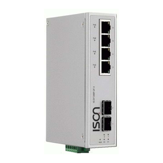
IS-DF306P Series
reasonable
the
equipment
is
may
cause
harmful
with
the
of
Council
Directive
laws
of
the
Member
1
protection
against
operated
in
a commercial
interference
to
requirements
relating
2004/108/EC
States
relating
harmful
radio
to
on
the
to
Advertisement
Table of Contents

Related Manuals for ISON IS-DF306P Series


Summary of Contents for ISON IS-DF306P Series
- Page 1 IS-DF306P Series Quick Installation Guide FCC MARKING This Equipment has been tested and found to comply with the limits for a Class A digital device, pursuant to part 15 of the FCC Rules. These limits designed provide reasonable protection against...
-
Page 2: Housing Dimension
Introduction This rugged designed Industrial Ethernet switch / Industrial Fast Ethernet 4 port POE Injectors, comply with IEEE802.3af and IEEE802.3at, has pass many rigorous environmental test. It delivers 30watts (Max 36watts) power per POE port. And it can generate t otal 126 watts power to PD devices. - Page 3 MODELS – Industrial Fast Ethernet 4 port Injector, 48VDC input This industrial high power POE+ is designed for multiple applications, especially for vehicle surveillance, IP surveillance, and traffic monitoring and for a broad range of outdoor applications. It can be used as a stand-alone device for buses, trucks for Surveillance purposes.
-
Page 4: Installation Package
Installation package This unit can be installed by din-rail mounted or wall-mounted. Din-rail brackets and wall-mounted bracket are included. Din Rail Bracket x 1 Wall mount bracket x 2 6 pin Terminal Block x1 Power connection This unit provides 6 pin terminal block. The POE port can be operated from 44-56VDC power source. The VDC power range can be 48VDC only or lower, or wide range from 44-56VDC. -
Page 5: Dip Switch Function
Dip switch function This unit is equipped with dip switches, located on the front panel. Adjusting the dip switches will change the default function of this unit. This unit has set to manufacturer default as: Port 5 SFP and the speed is set to 1000M for both port 1 and port 2 SFP ports. -
Page 6: Specification
Specification: IEEE 802.3 10Base-T Ethernet IEEE 802.3u 100Base-TX Fast Ethernet IEEE 802.3ab 1000Base-T Gigabit Ethernet IEEE Standard IEEE 802.3z 1000Base-X Gigabit Ethernet IEEE802.3x Flow Control and Back Pressure, IEEE802.3af for POE IEEE802.3at for POE+ Back-plane (Switching Fabric): 12Gbps Switch Architecture Store and Forward Data Processing IEEE 802.3x Flow Control and Back Pressure... - Page 7 Relay outputs with current carrying capacity of 1 A @24VDC, Alarm Relay Contact Relay in short circuit mode when 2 powers are connected. in open circuit mode when only one power supply is connected Ethernet Switch power input Ethernet switch power input 9VDC -56VDC input Voltage 44VDC-56VDC.
Need help?
Do you have a question about the IS-DF306P Series and is the answer not in the manual?
Questions and answers