Table of Contents
Advertisement
Quick Links
INTRODUCTION AND THEORY OF OPERATION ............................................................................2
ASSEMBLY NUMBER EXPLANATION..............................................................................................2
WINCH MODEL CODES ......................................................................................................................2
!WARNING!...........................................................................................................................................3
MAINTENANCE ....................................................................................................................................5
GENERAL DISASSEMBLY .................................................................................................................6
A. MOTOR DISASSEMBLY ................................................................................................................................................... 7
B. BRAKE SECTION DISASSEMBLY ................................................................................................................................... 7
C. DRUM SECTION DISASSEMBLY..................................................................................................................................... 8
D. GEAR SECTION DISASSEMBLY ................................................................................................................................... 10
E. INPUT PLANET SET DISASSEMBLY ............................................................................................................................. 11
F. OUTPUT PLANET SET DISASSEMBLY ......................................................................................................................... 12
GENERAL ASSEMBLY......................................................................................................................13
G. OUTPUT PLANET SET ASSEMBLY............................................................................................................................... 13
H. INPUT PLANET SET ASSEMBLY................................................................................................................................... 14
I. GEAR END ASSEMBLY.................................................................................................................................................... 15
J. DRUM SECTION ASSEMBLY.......................................................................................................................................... 16
K. BRAKE SECTION ASSEMBLY........................................................................................................................................ 17
L. MOTOR ASSEMBLY........................................................................................................................................................ 18
TROUBLESHOOTING........................................................................................................................19
RUFNEK 45 BILL OF MATERIAL .....................................................................................................20
VISCOSITY CHART............................................................................................................................23
TORQUE SPECIFICATIONS CHART................................................................................................24
RUFNEK 45 ISOMETRIC DRAWING ................................................................................................25
SEL-0034-003.DOC
REV-0
RUFNEK 45
SERVICE MANUAL
DESIGN SERIES 003
Advertisement
Table of Contents

Related Manuals for Tulsa Rufnek Intelliguard 45


Summary of Contents for Tulsa Rufnek Intelliguard 45
-
Page 1: Table Of Contents
DESIGN SERIES 003 RUFNEK 45 SERVICE MANUAL INTRODUCTION AND THEORY OF OPERATION ................2 ASSEMBLY NUMBER EXPLANATION....................2 WINCH MODEL CODES ........................2 !WARNING!............................3 MAINTENANCE ............................5 GENERAL DISASSEMBLY .........................6 A. MOTOR DISASSEMBLY ..............................7 B. BRAKE SECTION DISASSEMBLY ........................... 7 C. DRUM SECTION DISASSEMBLY............................. 8 D. -
Page 2: Introduction And Theory Of Operation
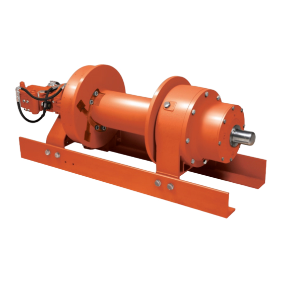
INTRODUCTION AND THEORY OF OPERATION The Rufnek series planetary winch is designed to use a high-speed gear motor, driving through a multiple disc brake, through two planet sets to the cable drum. The multiple disc brake is spring applied and hydraulically released through a port in the brake housing. -
Page 3: Warning
!W AR NI NG ! FAILURE TO HEED THE FOLLOWING WARNINGS MAY RESULT IN SERIOUS INJURY OR DEATH. The safety of the winch operator and ground personnel should always be of great concern, and all necessary precautions to insure their safety must be taken. The primary mover and the winch must be operated with care and concern for the equipment and the environment and with a thorough knowledge of the equipment and its performance capabilities must be understood. - Page 4 Operator: Must read and understand the operating and service manual. Both the SERVICE MANUAL and OPERATING AND MAINTENANCE MANUAL are available online at http://www.team-twg.com/TulsaWinch/ Must never lift or move people with this winch. This winch is not designed or intended for any use that involves moving people. Must stay clear of the load at all times.
-
Page 5: Maintenance
MAINTENANCE Tulsa Rufnek series planetary winches, like any other piece of machinery, need to be periodically serviced and well maintained to insure proper operation. Good maintenance consists of four steps. 1. A daily inspection to insure that there are no oil leaks present, all mounting bolts and other fasteners are tight, and that the wire rope is in good condition. -
Page 6: General Disassembly
GENERAL DISASSEMBLY A. MOTOR DISASSEMBLY 1. Drain the oil from the brake assembly by 5. Remove the counterbalance valve (50) from removing the plug (81) from bottom of brake the counterbalance block (32) and inspect the cover (2). metering hole to make sure it is not obstructed. -
Page 7: Brake Section Disassembly
B. BRAKE SECTION DISASSEMBLY 1. Evenly remove the four capscrews (3) that should measure no less than 0.055-in. thick hold the brake cover (2) in place. Spring and stator plates should measure no less than pressure will raise the cover up as the 0.068-in thick. -
Page 8: Drum Section Disassembly
C. DRUM SECTION DISASSEMBLY 1. To remove the drum, first disconnect the cable which frame the mounting bolts are on for re- from the U-bolt (35) and lay aside. If removing assembly. Inspect and replace if needed. the drum from the motor end with the motor and brake disassembled, first remove cotter 3. - Page 9 CLUTCH INSPECTION...
-
Page 10: Gear Section Disassembly
D. GEAR SECTION DISASSEMBLY 3. Remove the end cover (55) by removing eight capscrews (21). To remove the output gear set (40), the drum must first be removed, see 4. Inspect the o-rings (36 & 59) for wear and DRUM DISASSEMBLY section on replace if necessary. -
Page 11: Input Planet Set Disassembly
E. INPUT PLANET SET DISASSEMBLY 1. Remove the retaining rings (41-5) from the 3. With planet gears out, remove the plate (41-7). planet pins (41-6). Remove the pins from the carrier (41-1) by carefully tapping them out. 4. Inspect the parts for wear or damage and replace if necessary. -
Page 12: Output Planet Set Disassembly
F. OUTPUT PLANET SET DISASSEMBLY 1. Remove the retaining rings (40-4) from the 4. Inspect the parts for wear or damage and planet pins (40-3). replace if necessary. 2. Remove the pins (40-3) from the carrier (40-1) 5. With planet gears out, remove the plate (40-5) by carefully tapping them out. -
Page 13: General Assembly
GENERAL ASSEMBLY G. OUTPUT PLANET SET ASSEMBLY 1. Insert the output shaft (40-9) into the carrier 3. Being careful to line up the thrust washers (40-1) and install the retaining ring (40-7). (40-8) and bearings (40-6) with the planet pins (40-3), press the pin into the carrier (40-1). -
Page 14: Input Planet Set Assembly
H. INPUT PLANET SET ASSEMBLY 1. Insert the thrust plate (41-7) into the carrier 3. Replace the retaining rings (41-5). (41-1) along with the gears (41-3), bearings (41-2), and washers (41-4). 2. Being careful to line up the thrust washers (41-4) and bearings (41-2) with the planet pins (41-6), press the pin into the carrier (41-1). -
Page 15: Gear End Assembly
I. GEAR END ASSEMBLY 1. Bolt the gear housing (60) loosely into both against the output gear set (40) and engaged frames (64 , 65). with the output sun gear (47). Put the outer thrust washer (43) in place and slide the input 2. -
Page 16: Drum Section Assembly
J. DRUM SECTION ASSEMBLY 1. After inspecting and replacing the necessary drum is supported by both the brake and gear parts, install the bushing (4) onto the output housings. The air line from the brake band air shaft (40-9). cylinder can be attached at this time. 2. -
Page 17: Brake Section Assembly
K. BRAKE SECTION ASSEMBLY Dip friction discs in lightweight Non-EP oil before installation. Install the piston (5) into the brake housing (20) and gently tap it down until it is seated making sure not to damage the o-rings (8-10) Re-assemble driver/clutch assembly, or back-up rings (9-11). -
Page 18: Motor Assembly
L. MOTOR ASSEMBLY 1. Install the o-ring (98) onto the motor (1). 3. Install the counterbalance valve (50) into the Attach the motor (1) to the brake cover (2) counter-balance block (32). using four capscrews (88). Tighten the capscrews to the proper torque specification 4. -
Page 19: Troubleshooting
TROUBLESHOOTING FAILURE PROBABLE CAUSE Winch won’t hold load. a) Excessive back pressure in the system. Check the system for restrictions and reduce the backpressure. b) Brake discs are worn out. Replace brake discs. c) Winch clutch is slipping. Inspect the clutch and driver for wear and replace worn parts. -
Page 20: Rufnek 45 Bill Of Material
RUFNEK 45 BILL OF MATERIAL 81865003-BOM MAY 2006 Item Qty. Description 43399 HYDRAULIC MOTOR 43925 BRAKE COVER 28060 CAPSCREW 43234 BUSHING 42942 BRAKE PISTON 33094 O-RING 43938 BRAKE SPRING 32186 O-RING 42337 RING 42335 O-RING 42336 RING 42148 STATOR PLATE 32765 FRICTION DISC 44332... - Page 21 RUFNEK 45 BILL OF MATERIAL CONTINUED 40-2 43248 OUTPUT PLANET GEAR 40-3 42951 PLANET PIN 40-4 41716 RETAINING RING 40-5 43025 GEARSET PLATE 40-6 41717 BEARING 40-7 43702 RETAINING RING 40-8 939249 RACE 40-9 43239 OUTPUT SHAFT 4255 INPUT GEARSET 41-1 43245 INPUT CARRIER...
- Page 22 RUFNEK 45 BILL OF MATERIAL CONTINUED 20525 CAPSCREW 20521 20518 LOCKWASHER 42955 MOUNTING BRACKET 42978 O-RING PLUG 13050 BREATHER 42033 SWIVEL TEE 40280 FITTING 42438 STRAIGHT BRANCH TEE 42495 HOSE ASSEMBLY 43459 HOSE ASSEMBLY 21684 PIPE PLUG 27088 RETAINING RING OMIT 43834 AIR SHIFT KIT...
-
Page 23: Viscosity Chart
VISCOSITY CHART... -
Page 24: Torque Specifications Chart
TORQUE SPECIFICATIONS CHART Plated Lubricated Plated Lubricated SAE Grade SAE Grade SAE Grade SAE Grade SAE Grade Grade 5 Torque Torque Torque *(Ft- Torque *(Ft- Torque Torque *(Ft- Nominal Size *(Ft-Lbs) *(Ft-Lbs) Lbs) Lbs) *(Ft-Lbs) Lbs) 5/16 5/16 7/16 7/16 9/16 9/16 1019... -
Page 25: Rufnek 45 Isometric Drawing
RUFNEK 45 ISOMETRIC DRAWING DO NOT USE MAGNETS ON OR AROUND WINCH. PO Box 1130 Jenks OK 74037-1130 USA Phone: 918-298-8300 www.dovertwg.com...
Need help?
Do you have a question about the Rufnek Intelliguard 45 and is the answer not in the manual?
Questions and answers