Table of Contents
Advertisement
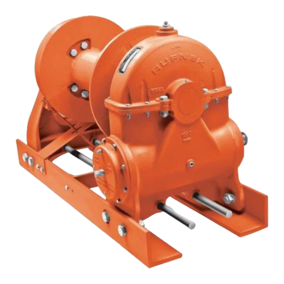
RUFNEK 100
SERVICE MANUAL
GENERAL INFORMATION .......................................................................................................................... 4
INTRODUCTION AND THEORY OF OPERATION ................................................................................................................. 4
ASSEMBLY NUMBER EXPLANATION ................................................................................................................................... 4
WINCH BREAK-IN .................................................................................................................................................................. 4
MODEL CODES ........................................................................................................................................... 5
MAINTENANCE............................................................................................................................................ 6
OIL LEVELS............................................................................................................................................................................ 7
BRAKE IDENTIFICATION AND ADJUSTMENT ...................................................................................................................... 8
DISASSEMBLY .......................................................................................................................................... 10
DRUM BRAKE DISASSEMBLY............................................................................................................................................. 10
ADJUSTABLE OIL BRAKE DISASSEMBLY.......................................................................................................................... 11
NON-ADJUSTABLE BRAKE DISASSEMBLY ....................................................................................................................... 12
RUFNEK BRAKE DISASSEMBLY......................................................................................................................................... 13
CLUTCH AND DRUM DISASSEMBLY.................................................................................................................................. 14
GEARBOX DISASSEMBLY................................................................................................................................................... 15
GEAR INSPECTION INSTRUCTIONS .................................................................................................................................. 16
ASSEMBLY ................................................................................................................................................ 17
GEARBOX ASSEMBLY ........................................................................................................................................................ 17
DRUM BRAKE ASSEMBLY .................................................................................................................................................. 18
ADJUSTABLE OIL BRAKE ASSEMBLY................................................................................................................................ 19
NON-ADJUSTABLE OIL BRAKE ASSEMBLY....................................................................................................................... 20
RUFNEK ADJUSTABLE OIL BRAKE ASSEMBLY ................................................................................................................ 21
CLUTCH AND DRUM ASSEMBLY........................................................................................................................................ 22
TROUBLESHOOTING................................................................................................................................ 23
BILL OF MATERIAL................................................................................................................................... 24
ADJUSTABLE BRAKE BILL OF MATERIAL ........................................................................................... 27
NON ADJUSTABLE BRAKE BILL OF MATERIAL .................................................................................. 27
RUFNEK BRAKE BILL OF MATERIAL..................................................................................................... 28
TORQUE SPECIFICATIONS CHART ........................................................................................................ 29
CLUTCH INSPECTION .............................................................................................................................. 30
ISOMETRIC VIEW ...................................................................................................................................... 31
ADJUSTABLE BRAKE, HYDRAULIC MOTOR, & CLUTCH POSITION INDICATOR VIEWS................ 32
SEL-0049-001.DOC
REV-0 JAN 2006
AND
MODEL 80
DESIGN SERIES 001
Advertisement
Table of Contents

Subscribe to Our Youtube Channel
Related Manuals for Tulsa Rufnek 100


Summary of Contents for Tulsa Rufnek 100
-
Page 1: Table Of Contents
DESIGN SERIES 001 RUFNEK 100 MODEL 80 SERVICE MANUAL GENERAL INFORMATION .......................... 4 INTRODUCTION AND THEORY OF OPERATION ......................... 4 ASSEMBLY NUMBER EXPLANATION ........................... 4 WINCH BREAK-IN .................................. 4 MODEL CODES ............................5 MAINTENANCE............................6 OIL LEVELS.................................... 7 BRAKE IDENTIFICATION AND ADJUSTMENT ........................8 DISASSEMBLY ............................ -
Page 2: Rufnek
FAILURE TO HEED THE FOLLOWING WARNINGS MAY RESULT IN SERIOUS INJURY OR DEATH. The safety of the winch operator and ground personnel should always be of great concern, and all necessary precautions to insure their safety must be taken. The primary mover and the winch must be operated with care and concern for the equipment and the environment. - Page 3 Operator: Must read and understand the operating and service manual. Both the SERVICE MANUAL and OPERATING AND MAINTENANCE MANUAL are available online at http://www.team-twg.com/TulsaWinch/ Must never lift or move people with this winch. This winch is not designed or intended for any use that involves moving people. Must stay clear of the load at all times.
-
Page 4: General Information
INTRODUCTION AND THEORY OF OPERATION INTRODUCTION AND THEORY OF OPERATION The Tulsa worm gear winch is operated by turning the input of the worm using a hydraulic motor or PTO driven sprocket and chain. The winch utilizes the adjustable, spring applied, multiple disc oil brake that activates only during pay-out to provide maximum efficiency during pay-in. -
Page 5: Model Codes
MODEL CODES MODEL CODES MODEL CODES MODEL CODES THE RUFNEK SERIES WINCHES ARE ONLY RN100 W M R F O M X AVAILABLE WITH LEFT HAND GEARS. Motor Type Gear Type 1. Single Speed Gear Motor W=Worm 2. Two Speed Gear Motor P=Planetary 3. -
Page 6: Maintenance
6 months of normal usage. If your winch is mounted with a drum brake, do not fill the brake with oil. • Tulsa Winch recommends that the oil level in the gearbox be checked and adjusted as part of the pre-use inspection. If the oil level drops frequently or oil leakage is detected during an inspection, maintenance should be performed to correct any problems. -
Page 7: Oil Levels
OIL LEVELS OIL LEVELS OIL LEVELS OIL LEVELS GEARBOX FILL/VENT GEARBOX OIL LEVEL GEARBOX OIL DRAIN BRAKE FILL/VENT BRAKE OIL DRAIN BRAKE OIL LEVEL... -
Page 8: Brake Identification And Adjustment
AND ADJUSTMENT AND ADJUSTMENT In general, worm brakes on Tulsa winches should be set to hold the load you are currently working with. Excessive brake torque will result in excessive heat generation and brake wear. The best way to insure proper brake adjustment is to pull the cable tight against the load and stop to ensure the brake holds. - Page 9 These brakes require no regular adjustment. The direction of braking for all multiple disc brakes can be changed by removing the cam clutch, turning it over, and re-installing it. For detailed service instructions, contact your Tulsa Winch distributor or the factory. ______________________________________________________________________ RUFNEK ADJUSTABLE MULTIPLE DISC OIL BRAKE This brake is the Rufnek version of the adjustable oil brake.
-
Page 10: Disassembly
DISASSEMBLY DISASSEMBLY DISASSEMBLY DISASSEMBLY DRUM DRUM BRAKE DISASSEMBLY DRUM DRUM BRAKE DISASSEMBLY BRAKE DISASSEMBLY BRAKE DISASSEMBLY 1. Loosen the capscrews (31). 7. Inspect parts as follows, replace if necessary: 2. Remove the capscrews (88) from the cover (86). A. Inspect the brake shoes (98) for wear. -
Page 11: Adjustable Oil Brake Disassembly
ADJUSTABLE OIL BRAKE DISASSEMBLY ADJUSTABLE OIL BRAKE DISASSEMBLY ADJUSTABLE OIL BRAKE DISASSEMBLY ADJUSTABLE OIL BRAKE DISASSEMBLY 1. Drain the oil from the brake by 5. Remove the spring (10). Grasp the removing the drain plug (21). brake driver (8) and remove the brake components. -
Page 12: Non-Adjustable Brake Disassembly
NON- - - - ADJUSTABLE BRAKE DISASSEMBLY ADJUSTABLE BRAKE DISASSEMBLY ADJUSTABLE BRAKE DISASSEMBLY ADJUSTABLE BRAKE DISASSEMBLY 1. Place a container underneath the 4. Inspect the stator plates (12), friction brake to catch the oil when the cover discs (13), and retaining ring (11) for is removed. -
Page 13: Rufnek Brake Disassembly
RUFNEK RUFNEK ADJUS ADJUSTABLE OIL TABLE OIL BRAKE DISASSEMBLY BRAKE DISASSEMBLY RUFNEK RUFNEK ADJUS ADJUS TABLE OIL TABLE OIL BRAKE DISASSEMBLY BRAKE DISASSEMBLY 1. Remove the bottom drain plug (9) to 5. Inspect parts as follows, replace if drain oil from brake. necessary: 2. -
Page 14: Clutch And Drum Disassembly
CLUTCH AND DRUM DISASSEMBLY CLUTCH AND DRUM DISASSEMBLY CLUTCH AND DRUM DISASSEMBLY CLUTCH AND DRUM DISASSEMBLY 1. Remove the cotter keys (20) and 7. Remove the brake band assembly clevis pins (19) holding the rod (5) by removing the capscrews (27), assembly (24, 28, 38) in place. -
Page 15: Gearbox Disassembly
GEAR GEAR GEAR GEARBOX BOX DISASSEMBLY DISASSEMBLY DISASSEMBLY DISASSEMBLY 1. Supporting the end of the output sliding off the bearing retainer (59), shaft (78) with a hoist, remove the along with the two sets of angular housing cover (80) by removing bearings (58). -
Page 16: Gear Inspection Instructions
GEAR INSPECTION INSTRUCTIONS GEAR INSPECTION INSTRUCTIONS GEAR INSPECTION INSTRUCTIONS GEAR INSPECTION INSTRUCTIONS LAND Check gear wear by removing the cover and visually inspecting the bronze gear. If the gear is worn such that there is no visible land on the throat of the gear between the gear flanks as shown in picture above the gear should be replaced. -
Page 17: Assembly
ASSEMBLY ASSEMBLY ASSEMBLY ASSEMBLY GEARBOX GEAR BOX ASSEMBLY ASSEMBLY GEAR GEAR ASSEMBLY ASSEMBLY 1. Press the angular bearings (58) into eight capscrews (53), using gasket the bearing retainer (59), then slide (51). Install the key (65) into the the bearing retainer and bearings worm (60) shaft. -
Page 18: Drum Brake Assembly
DRUM DRUM DRUM DRUM BRAKE ASSEMBLY BRAKE ASSEMBLY BRAKE ASSEMBLY BRAKE ASSEMBLY 1. Press the oil seal (37) into the end 3. If removed, reattach the cam (85) to cap (93). Install the gasket (92), and the brake cover (86) using two attach the end cap (93) to the capscrews (31) and washers (87). -
Page 19: Adjustable Oil Brake Assembly
ADJUSTABLE ADJUSTABLE ADJUSTABLE ADJUSTABLE OIL OIL BRAKE AS BRAKE AS BRAKE ASSEMBLY BRAKE AS SEMBLY SEMBLY SEMBLY 1. Press the oil seal (19) into the 4. Install the spring (10) and then press reaction housing (2), then mount the the adjusting mechansim assembly reaction housing to the gearbox with (items 9, 22, 23) into the brake cover six capscrews (12), using a gasket... -
Page 20: Non-Adjustable Oil Brake Assembly
NON- - - - ADJUSTABLE ADJUSTABLE ADJUSTABLE ADJUSTABLE OIL OIL BRAKE ASSEMBLY BRAKE ASSEMBLY BRAKE ASSEMBLY BRAKE ASSEMBLY 1. Press the oil seal into the reaction 4. Install the spring (14) then press the housing (3), then mount the reaction washer (16) into the brake cover housing to the gearbox with six (17). -
Page 21: Rufnek Adjustable Oil Brake Assembly
RUFNEK ADJUSTABLE OIL BRAKE ASSEMBLY FNEK ADJUSTABLE OIL BRAKE ASSEMBLY FNEK ADJUSTABLE OIL BRAKE ASSEMBLY FNEK ADJUSTABLE OIL BRAKE ASSEMBLY 1. Press the oil seal (1) into the reaction brake cover (7) and attach the brake housing (2). Attach the reaction cover to the gearbox with eight housing to the gearbox with eight evenly installed capscrews (11) and... -
Page 22: Clutch And Drum Assembly
CLUTCH AND DRUM ASSEMBLY CLUTCH AND DRUM ASSEMBLY CLUTCH AND DRUM ASSEMBLY CLUTCH AND DRUM ASSEMBLY 1. Install bushings (12) into drum (14). 4. Install the end bracket (32) and the Install the drum (14) onto the output yoke assembly or clutch position shaft (78). -
Page 23: Troubleshooting
TROUBLESHOOTING TROUBLESHOOTING TROUBLESHOOTING TROUBLESHOOTING FAILURE PROBABLE CAUSE Clutch handle won’t latch a) Clutch jaws aren’t aligned. Align the jaws by rotating drum. b) Damaged yoke or linkage. Replace the yoke or clutch Oil leaks from housing a) Seal damaged or worn. Replace the seal(s). -
Page 24: Bill Of Material
BILL OF MATERIAL BILL OF MATERIAL BILL OF MATERIAL BILL OF MATERIAL BOM DATED SEPTEMBER 2005 DESCRIPTION 20886 CAPSCREW 21128 GREASE ZERK 20579 END CAP 20129 BRACKET 939310 BRAKE BAND ASSEMBLY 20603 WASHER 20591 CLUTCH 23600 CLUTCH 21214 21180 U BOLT 21644 CAPSCREW 21360... - Page 25 BILL OF MATERIAL BILL OF MATERIAL BILL OF MATERIAL BILL OF MATERIAL CONTINUED CONTINUED CONTINUED CONTINUED DESCRIPTION 20621 OIL SEAL 20266 CAPSCREW 20583 COVER 20637 GASKET OMIT 30204 CAPSCREW 20625 939232 WASHER OMIT OMIT 20620 BEARING 20581 HOUSING 20618 LEFT HAND MECHANICALLY DRIVEN WORM 20534 RIGHT HAND MECHANICALLY DRIVEN WORM 40695...
- Page 26 BILL OF MATERIAL BILL OF MATERIAL BILL OF MATERIAL BILL OF MATERIAL CONTINUED CONTINUED CONTINUED CONTINUED DESCRIPTION 20314 20536 HOUSING 20776 BEARING 20117 GASKET 939296 END CAP 939261 CAPSCREW 20542 BRAKE DRUM 20313 WASHER 20312 939311 BRAKE SHOE ASSEMBLY 41412 MOTOR (57.4 CUBIC INCH DISPLACEMENT) 40487 MOTOR (40.6 CUBIC INCH DISPLACEMENT)
-
Page 27: Adjustable Brake Bill Of Material
ADJUSTABLE ADJUSTABLE BRAKE BILL OF MATERIAL BRAKE BILL OF MATERIAL ADJUSTABLE ADJUSTABLE BRAKE BILL OF MATERIAL BRAKE BILL OF MATERIAL DESCRIPTION 33420 32946 REACTION HOUSING 42695 RETAINING RING 12208 BUSHING 13050 BREATHER 32942 COUPLER 33407 CAM CLUTCH 31076 RETAINING RING 3687 DRIVER 42692... -
Page 28: Rufnek Brake Bill Of Material
RUFNEK BRAKE BILL OF MATERIAL RUFNEK BRAKE BILL OF MATERIAL RUFNEK BRAKE BILL OF MATERIAL RUFNEK BRAKE BILL OF MATERIAL DESCRIPTION 20775 OIL SEAL 32946 REACTION HOUSING 12208 BUSHING 13050 BREATHER 41411 O-RING 41406 ADJUSTING MECHANISM 43974 BRAKE COVER 42692 SPRING PLATE 21684 PLUG... -
Page 29: Torque Specifications Chart
TORQUE SPECIFICATION TORQUE SPECIFICATION TORQUE SPECIFICATION TORQUE SPECIFICATIONS CHART S CHART S CHART S CHART Plated Lubricated Plated Lubricated Grade 5 Grade 5 Grade 5 Grade 8 Grade 8 Grade 8 Torque Torque Torque Torque Torque Torque Nominal Size *(Ft- *(Ft- *(Ft- *(Ft-Lbs) -
Page 30: Clutch Inspection
CLUTCH INSPECTION CLUTCH INSPECTION CLUTCH INSPECTION CLUTCH INSPECTION... -
Page 31: Isometric View
ISOMETRIC ISOMETRIC ISOMETRIC ISOMETRIC VIEW VIEW VIEW VIEW FOR ADJUSTABLE OIL BRAKE AND HYDRAULIC MOTOR, SEE PAGE 32... -
Page 32: Adjustable Brake, Hydraulic Motor, & Clutch Position Indicator Views
ADJUSTABLE BRAKE, HY ADJUSTABLE BRAKE, HY ADJUSTABLE BRAKE, HY ADJUSTABLE BRAKE, HYDRAULIC MO DRAULIC MO DRAULIC MO DRAULIC MOTOR, & CLUTCH POSITI TOR, & CLUTCH POSITI TOR, & CLUTCH POSITION INDICATOR TOR, & CLUTCH POSITI ON INDICATOR ON INDICATOR ON INDICATOR VIEWS VIEWS VIEWS VIEWS...
Need help?
Do you have a question about the Rufnek 100 and is the answer not in the manual?
Questions and answers